 فارسی
فارسی  English
 Upon successful completion of this lesson, you will be able to:
- List the most commonly used CNC
- Determine spindle rotational
- Interpret a chip formation
- Define chip
- Distinguish between climb and conventional
- Compute cutting speeds and feeds for a specified tool, material and operation using reference tables.
Overview
A wide range of tool types and configurations are available for CNC milling machines. Discussing every type, variation and use is beyond the scope of this course. This chapter introduces the most commonly used tools for prototype and short run production machining. Any tool supply catalog will list many others.
- End mills (Flat, Ball, Bull and Chamfer)Face mill
- Corner Rounding tools
- Slot Tools
- Spot−Center Drill
- Twist Drill
- Tap
- Reamer
- Counterbore
3.1 - End Mills
Milling tools include flat, ball, bull nose and chamfer.

Figure 1: Mill Tool Nose Types
Flat nose mills are used for milling 2D contours and pockets. Ball nose mills are used for 3D milling. Bull nose end mills have a radius corner. They are used to create a fillet on the bottom of a wall. Because they are sturdier than an end mill they are also sometimes used for roughing operations. Chamfer mills have an angled nose used to create a chamfer or to de−burr parts.
جهت خرید قطعات سی ان سی و اطلاع از قیمت های لوازم cnc اینجا کلیک کنید.
Number of Flutes
Milling tools usually have either two or four cutting flutes. Two flute cutters provide more chip clearance when milling in close areas. Four flute mills are more rigid, can be fed faster, and are preferred when greater chip clearance is not required, such as when milling an outside contour.
Center-Cutting End Mills
Milling tools are either center cutting or non−center cutting. Center cutting mills can plunge straight down into material, while non−center cutting tools cannot.
Figure 2 below shows the cutting end view of a center cutting and non−center cutting end mill. Notice that the cutting edges of the center cutting end mill continues to the center of the tool. The center of the other has a small hole at the center. Non−center cutting end mills require a pilot hole, ramping or helical motion to plunge into material.
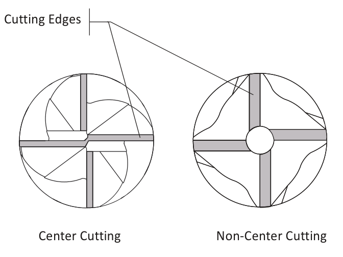
Figure 2: End View of Center and Non-Center Cutting End Mill
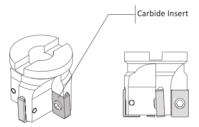
Figure 3: Face Mill
3.2 Face Mill
A face mill has cutting inserts that are replaced when worn. They are rigid, may have up to eight or more cutting edges, and can remove material quickly. They are often used for the first machining operation to quickly create a flat finished face on the part.
3.3 Corner Radius Tool
Corner radius (also called Corner Round) tools are used to place a fillet on the outside corner of a part.
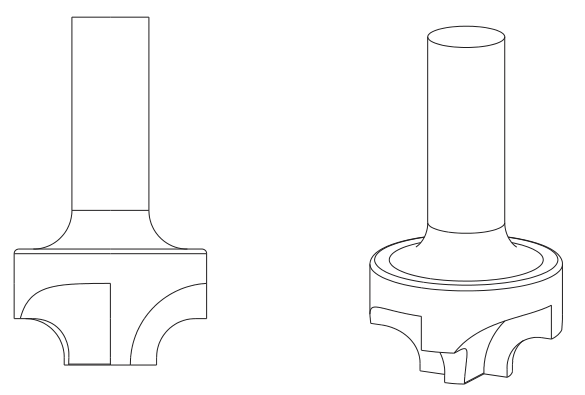
Figure 4: Corner Round Tool
3.4 Slot Mill/Slotting Saw
Slot mills include side milling cutters, slitting saws, and Woodruff keyset cutters. Slitting saws and side milling cutters are installed on a special arbor. Woodruff cutters are single piece tools used for creating slots and undercuts that can be held in a standard tool holder.
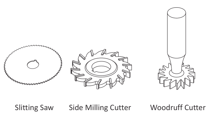
Figure 5: Slot Tools
3.5 Hole-Making Tools
Center-Spot Drills
Center (spotting) drills are short and very rigid drills used to create a conic on the face of the part. Because they come to a sharp point and resist bending, they locate the hole precisely. The conic helps prevent the subsequent drill from wobbling and ensure the drill is located precisely and drills straight down.
Countersink drills are used to create the conical face for a machine screw. Combined spotting−countersinks are used to create a screw clearance hole and countersink in one operation.
جهت خرید قطعات سی ان سی و اطلاع از قیمت های لوازم cnc اینجا کلیک کنید.
There are many different sizes and tip angles of center, countersink, and combined drills. Be sure the tip angle of the countersink matches the included angle of the machine screw, and that the drill diameter is greater than the screw head diameter.
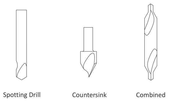
Figure 6: Countersink and Center Drill
Twist Drill
Twist drills are available in many diameters and lengths. Usually made of high speed steel, carbide, or cobalt, they may also be coated with titanium nitride (TiN) for longer life. The tip angle of most twist drills is 118 degrees.
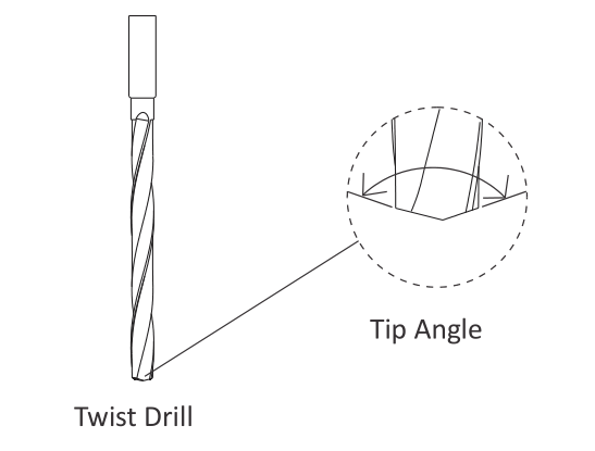
Figure 7: Twist Drill
Taps
Cutting taps form threads by shearing material away. Form taps (roll taps) form the thread by forming the metal to shape. Form taps produce no chips and are used for soft materials including aluminum, copper, brass and plastics.
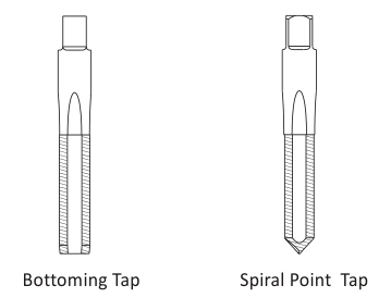
Figure 8: Taps
Bottoming taps are used to tap blind holes. Spiral point taps push the chip ahead and out the bottom of a through hole.
Taps require a hole drilled to the correct size to ensure the thread is formed properly. For example, a ¼−20 cutting tap requires drilling a .201 (#7) hole. Refer to the drill chart in Appendix A to find the correct drill size for a specified thread size and fit.
Most CNC Machines support rigid tapping, which means the tap can be held in a rigid holder. The tap is advanced at a feed rate that matches the thread lead into the hole. The spindle then stops, reverses, and backs out of the hole.
Machines without rigid tapping require special tapping attachments. Always refer to the manufacturers’ instructions as the speed, feed, and other machining parameters for tapping attachments may be different that those for rigid tapping.
Reamer
Use reamers to create holes of precise shape and excellent surface finish. Reamed holes are usually accurate within .0002 inches diameter. For example, a reamer is used for holes used for ground pins and bushings.
Reamers require a specific size hole be drilled before use. Cutting speeds and feeds are also important. Remove too little or too much material and the hole will not be the correct size.
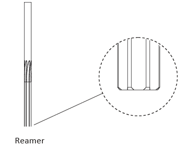
Figure 9: Reamer
Counterbore
A counterbore looks similar to a end mill with a pilot in the center. It is used to spot face holes, and the pilot ensures the spot face is centered on the hole.
Counterboring is not necessary when using a CNC machine. Rather, create a spot face using a pocket or circle mill tool path. This saves having to buy and stock counterbore tools and pilots, and the time required to load and set up the counterbore.
3.6 Cutting Tool Fundamentals
Rotation Direction
All tools (except left−handed taps) rotate clockwise (M3) when viewed from the machine spindle looking down at the part.
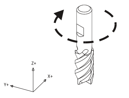
Figure 10: Clockwise Tool Rotation
Chip Formation
Cutting tools remove metal by shearing action as illustrated in Figure 11 below. As the tool advances into the material it causes a small amount of the material to shear away, forming a chip.
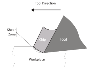
Figure 11: Chip Formation Diagram
Chip Load
The thickness of material sheared away by each cutting tooth is called the feed per tooth, or chip load. As the chip is ejected from the work area it carries with it some of the heat generated by the shearing process.
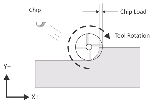
Figure 12: Chip Load
A methodology for calculating cutting speeds and feeds is presented later in this chapter. One of the best ways to validate cutting speeds and feeds is to observe the chips created by the machining process. Chips should be curled and may change color due to heating.
After gaining some experience machinists are able to adjust cutting speeds and feeds based in part on the size, shape, and color of chips and on the sound produced by the cutting process.
Climb vs. Conventional Milling
Milling tools can advance through the material so that the cutting flutes engage the material at maximum thickness and then decreases to zero. This is called Climb Milling.
Cutting in the opposite direction causes the tool to scoop up the material, starting at zero thickness and increasing to maximum. This is called Conventional Milling.
Conventional milling is used often on manual machines because backlash in the machine lead screws causes the tool to lurch when climb cutting. This is not a problem on CNC machines because they use ball screws.
جهت خرید قطعات سی ان سی و اطلاع از قیمت های لوازم cnc اینجا کلیک کنید.
Conventional milling causes the tool to rub against the cutting surface, work hardening the material, generating heat, and increasing tool wear. Raking chips across the finished surface also produces a poorer surface finish.
Unless specifically recommended by the tool manufacturer for the material being milled, always use climb milling on a CNC. Climb milling produces far less cutting pressure and heat, leaves a better surface finish, and results in longer tool life.
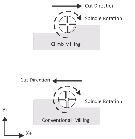
Figure 13: Climb vs. Conventional Milling
3.7 Cutting Speeds and Feeds Formulas
The tool moves through the material at a specified rotational speed, defined in revolutions per minute (RPM), and feed rate, defined in inches per minute (IPM). Probably the most vexing problem for the beginning CNC machinist is selecting proper cutting speeds and feeds. This selection is actually more difficult on a CNC than a manual mill because, with a manual mill, the operator can feel the cutting pressure and alter the feed based in part on the cutting force.
CNC mills require calculating speeds and feeds in advance. These speeds and feeds can, and often are, adjusted at the machine based on chip shape and color, cutting sound, and machine horsepower meter readings.
The best source of data about cutting speeds and feeds for a specific tool, application, and material is the tool supplier. Much of this data is found on manufacturer’s web sites or printed tooling catalogs. Tool sales representatives can be a valuable resource, so if you do a lot of machining, develop a good relationship with a knowledgeable representative.
Another source of speeds and feeds data is CADƒCAM software. These have become increasingly sophisticated and often provide good cutting data.
Yet even the best speed and feed data is just a starting point. Speeds and feeds require adjustment due to many factors including the maximum spindle speed or horsepower of the machine, rigidity of work holding, and the quality and condition of the machine tool itself.
The following pages provide cutting data for the most commonly machined materials and a methodology for calculating speeds and feeds. As always, use common sense. If the part is held by double sided tape, feeds based on vise work holding are probably too high. If the tool is very long and thin, speeds and feeds will likely require reduction.
Speed Formula
Milling machine cutting speeds are derived from the following formula:

Speed is the rotational frequency of the tool (Spindle Speed) in revolutions per minute (RPM).
SFM (Surface Feet per Minute) is the speed at which the material moves past the cutting edge (outside diameter) of the tool in feet per minute. SFM values depend on the tool type, tool material, and material being machined.
Circumference is the circumference of the cutting tool in feet.
How Speed Formula is Derived
Because cutting tools are defined by their diameter in inches, this formula is rewritten and simplified as follows:
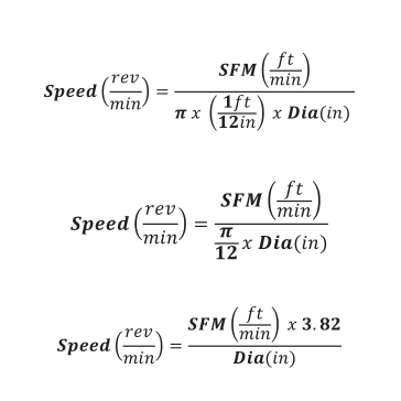
DIA is the tool diameter in inches.
3.82 is a constant derived from 12/n which converts the tool circumference in feet to diameter in inches.
Feed Formula
Cutting feeds are in (IPM) and use the following formula:

Feed is the linear feed of the tool through the material in inches per minute.
Speed is the result of the speed formula (Figure 15) in revolutions per minute.
CL is the chip load, or how much material each cutting edge of the tool removes per revolution. Chip load is sometimes referred to as feed per tooth (FPT) or inches per rev (IPR).
NumFlutes is the number of cutting flutes. (For a twist drill, this value is one.)
Tap Feed Formula
For tapping operations, feed rate is based on the number of threads per inch and feed rate:

Feed is the linear feed of the tool through the material in inches per minute.
Speed is the result of the previous formula in revolutions per minute.
TPI is the threads per inch of the tap. For example, the TPI of a ¼−20 tap is 20.
3.8 Speed/Feed Examples
Milling Speed/Feed Example
Problem: Calculate the cutting speed and feed for a milling operation given the following values:
|
Parameter |
Value |
|
Tool Diameter |
in 0.500 |
|
NumFlutes |
4 |
|
SFM |
ft/min 600 |
|
IPR |
in 0.005 |
Solution:
Step 1: Calculate RPM
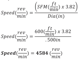
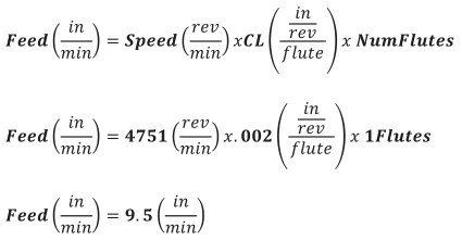
Step 2: Calculate IPM
Note: Round off milling speeds and feeds to the nearest integer.
Drill Speed/Feed Example
Problem: Calculate the cutting speed and feed for a drill operation given the following values:
|
Parameter |
Value |
|
Tool Diameter |
in 0.201 |
|
SFM |
ft/min 250 |
|
IPR |
in 0.002 |
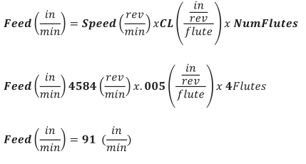
Solution:
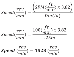
Step 1: Calculate RPM
Step 2: Calculate IPM
Note: Round off drilling feeds to the first decimal point.
Tap Speed/Feed Example
Problem: Calculate the cutting speed and feed for a ¼−24 tap operation given the following values:
|
Parameter |
Value |
|
Tool Diameter |
in 0.25 |
|
SFM |
ft/min 100 |
|
TPI |
24 |
Solution:
Step 1: Calculate RPM
Step 2: Calculate IPM
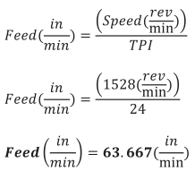
Note: Round off tapping feeds to three decimal points or the maximum number the machine allows.
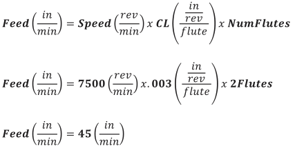
Maximum Spindle Speed Example
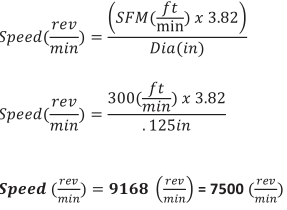
In cases where the calculated spindle speed exceeds the machine capabilities, program the maximum spindle speed of the machine and use this value in the feed calculation.
Problem: Calculate the cutting speed and feed for a milling operation given the following values:
|
Parameter |
Value |
|
Tool Diameter |
in 0.25 |
|
NumFlutes |
2 |
|
SFM |
ft/min 300 |
|
IPR |
in/rev0.003 |
|
RPM ماکزیمم |
rev/min7500 |
Solution:
Step 1: Calculate RPM
Step 2: Calculate IPM
3.9 Cutting Data
Tables on the following pages provide basic speed, feed and cutting data for some of the materials commonly used for prototypes. Use the tool manufacturer’s data instead whenever it is available.
|
Mill Cutting Speeds (SFM) surface ft/min |
||
|
Material |
HSS |
Carbide |
|
Aluminum |
600 |
800 |
|
Brass |
175 |
175 |
|
Delrin |
400 |
800 |
|
Polycarbonate |
300 |
500 |
|
Stainless Steel (303) |
80 |
300 |
|
Steel (4140) |
70 |
350 |
|
Drill Cutting Speeds (SFM) surface ft/min |
|
|
||
|
ماده |
مته کاری |
گشادکاری |
برقو |
قلاویز |
|
Aluminum |
300 |
200 |
150 |
100 |
|
Brass |
120 |
90 |
66 |
100 |
|
Delrin |
150 |
100 |
75 |
100 |
|
Polycarbonate |
240 |
160 |
120 |
100 |
|
Stainless Steel (303) |
50 |
35 |
25 |
35 |
|
Steel (4140) |
90 |
60 |
45 |
35 |
|
Cutting Feeds (IPR) in/rev |
|
|
|
||
|
Operation |
Tool Diameter Range (in) |
||||
|
|
<0.125 |
0.125-0.25 |
0.25-0.5 |
0.5-1 |
>1 |
|
Milling |
|
|
|
|
|
|
Aluminum |
0.002 |
0.002 |
0.005 |
0.006 |
0.007 |
|
Brass |
0.001 |
0.002 |
0.002 |
0.004 |
0.005 |
|
Delrin |
0.002 |
0.002 |
0.005 |
0.006 |
0.007 |
|
Polycarbonate |
0.001 |
0.003 |
0.006 |
0.008 |
0.009 |
|
Stainless Steel (303) |
0.0005 |
0.001 |
0.002 |
0.003 |
0.004 |
|
Steel (4140) |
0.0005 |
0.0005 |
0.001 |
0.002 |
0.003 |
|
|
|
|
|
|
|
|
Drilling |
0.002 |
0.004 |
0.005 |
0.010 |
0.15 |
|
|
|
|
|
|
|
|
Reaming |
0.005 |
0.007 |
0.009 |
0.012 |
0.015 |
Best Practice Machining Parameters
Best practice machining parameters for prototype and short−production milling are different than for mass production. Production machining is obsessed with minimizing run time and maximizing tool life because even small improvements per part can result in significant cost savings.
جهت خرید قطعات سی ان سی و اطلاع از قیمت های لوازم cnc اینجا کلیک کنید.
Prototype and short run production seeks to maximize reliability. Obviously, it does not make sense to risk breaking a tool or scrapping a part trying to save a few seconds if only making a few parts.
Tables 8 and 9 on the following pages list recommended machining parameters for prototypes. The values are relatively conservative and work well for materials and tool types listed on the previous pages.
For materials or tools not listed, consult cutting data from the tool manufacturer.
|
Recommended Machining Parameters |
||
|
Operation |
Parameter |
Value |
|
All |
Clearance Height |
1.0 inches |
|
All |
Feed Height |
0.1 inches |
|
All |
Rapid Height |
As needed to clear clamps and fixtures |
|
Mill (Roughing) |
Stepover (XY) |
50−80% of tool dia. |
|
Mill (Roughing) |
Stepdown (Z) |
25−50% of tool dia. |
|
Drill |
Peck Increment |
0.05 inches |
|
Spot Drill |
Dwell |
0.5 seconds |
|
Stock Finish Allowances (lnches) |
|
|
|
||
|
Operation |
Tool Diameter Range (in) |
||||
|
|
<0.125 |
0.125-0.25 |
0.25-0.5 |
0.5-1 |
>1 |
|
Milling (XY) |
0.001 |
0.005 |
0.015 |
0.020 |
0.020 |
|
Milling (Z) |
0.001 |
0.002 |
0.005 |
0.005 |
0.005 |
|
Reaming |
0.005 |
0.010 |
0.012 |
0.020 |
0.030 |
Troubleshooting Speed/Feed Problems
Do not make the mistake of thinking that the only option when encountering a machining problem is to reduce feed rate. Sometimes that is the worst thing to do and decreasing speed and increasing feed may be a better option.
Be methodical. When a problem occurs, stop. Analyze what is happening, draw on all available resources, and then devise a solution to correct the problem. The Machinery’s Handbook (Industrial Press Inc, 2008, New York, NY, ISBN: 978−8311−2800−5) contains extensive information about diagnosing and correcting cutting tool problems. This book is an essential reference for anyone using machine tools.