 فارسی
فارسی  English
 Upon successful completion of this lesson, you will be able to:
- Identify the elements of the Cartesian coordinate
- Explain the purpose of the Work Coordinate System (WCS) and considerations for its
- List the major elements of a closed−loop servo control mechanism.
- Identify the location and orientation of the machine coordinate
- Explain the purpose of the Fixture Offset
- Explain the purpose of the Tool Length Offset and how to set it using a scrap a 1− 2−3 block.
- Explain the purpose of the Fixture Offset Z and how it is set it using a 1−2−3 block and dial
- Name the two systems of units used in programming CNC machines
Overview
CNC motion is based on the Cartesian coordinate system. A CNC machine cannot be successfully operated without an understanding of the how coordinate systems are defined in CAM and CNC machine and how the systems work together.
This lesson begins with a review of the Cartesian coordinate system and then explains in detail how the coordinate systems between CAM and the CNC machine are related to each other. It also describes how the machine work coordinate system (WCS) is set on the CNC machine so the machine knows where the part is located within the work space.
جهت خرید قطعات سی ان سی و اطلاع از قیمت های لوازم cnc اینجا کلیک کنید.
It concludes with a discussion of tool length and diameter offsets. Length offsets are required to account for different tool lengths (how far a particular tool extends out of the holder). Diameter offsets are the key to highly precise machining where part tolerances can be maintained to an accuracy of .005 inches or less.
4.1 Cartesian Coordinate System
CNC motion is based on a 3D Cartesian coordinate system.
Number Line
The basis of this system is the number line marked at equal intervals. The axis is labeled (X, Y or Z). One point on the line is designated as the Origin. Numbers on one side of the line are marked as positive and those to the other side marked negative.
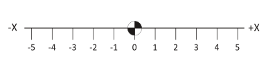
Figure 1: X-Axis Number Line.
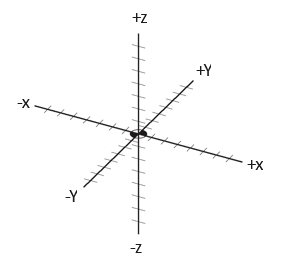
Figure 2: 3D Cartesian Coordinate System
3D Cartesian Coordinate System
The Cartesian coordinate system consists of three number lines, labeled X, Y and Z, set at 90 degree angles to each other as shown in Figure 2 below. The origin, or Datum, is where the three axes cross each other. The labels, orientations, and directions of the Cartesian coordinate system in Figure 2 are typical of most Vertical Machining Center (VMC).
Quadrants
Any two axes form a plane. Planes are named by the axes that define them. For example, Figure 3 shows the XY plane, which is the primary work plane for machining on a VMC. A plane can be divided into four quadrants, labeled I, II, III and IV with axes designations as shown in the illustration below.
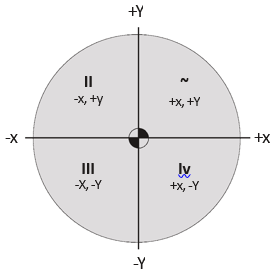
Figure 3: Quadrants
Units
CNC Programs can be written in either Inch or Metric units. The machine can be switched with a single code to accept either.
In the United States, most programming is using inch units because most tooling is in inches and machinists are more familiar with the inch measurement system. Even if the part is designed in metric, it is usually converted to inch units for machining and metric tools are used only when no inch equivalent is available (for example when creating metric tapped holes).
Table 1 lists the units and maximum precision for inch and metric data used by CNC machines.
|
Units and Precision |
||||
|
Data Type |
Inch Units |
Metric Units |
||
|
Coordinate |
inches |
0.0001 |
mm |
0.001 |
|
Speed |
rev/min |
1 |
rev/min |
1 |
|
Feed |
in/min |
1 |
mm/min |
1 |
|
Tap Feed |
in/min |
0.001 |
mm/min |
0.01 |
Table 1: Units and Precision
4.2 Vertical Milling Center (VMC) Machine Motion
CNC machines use a 3D Cartesian coordinate system. Figure 4 shows a typical VMC with the sheet metal covers removed to expose the movable parts.
Material to be machined is fastened to the machine table. This table moves in the XY−Plane. As the operator faces the machine, the X−Axis moves the table left−right. The Y−Axis moves the table forward−backward.
The machine column grips and spins the tool. The column controls the Z−axis and moves up−down.
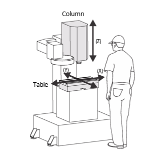
Figure 4: VMC Machine Motion
CNC Motion Control
Most CNC machines can position each axis within .0002 inches or less over the entire machining envelope. This accuracy is achieved in part by the use of a closed−loop servo mechanism, illustrated in Figure 5.
The machine control sends a motion signal, via a controller board, to a servomotor attached to each machine axis. This causes the servomotor to rotate a ball screw attached to the table or column, causing it to move. The actual position of the axis is continuously monitored and compared to the commanded position with feedback from a servo transmitter attached to the ball screw.
Ball screws have almost no backlash, so when the servo reverses direction there is almost no lag between a commanded reversing motion and corresponding change in table direction. CNC controls employ electronic compensation to adjust for any minor backlash that may exist.
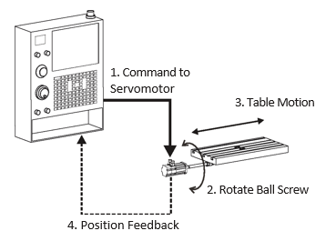
Figure 5: Closed Loop Servo Mechanism
CNC Machine Coordinates
The CNC Machine Coordinate System is illustrated in Figure 6. The control point for the Machine Coordinate System is defined as the center−face of the machine spindle.
The Origin point for the machine coordinate system is called Machine Home. This is the postion of the center− face of the machine spindle when the Z−axis is fully retracted and the table is moved to its limits near the back− left corner.
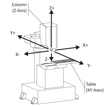
Figure 6: VMC Machine Coordinate System (At Home Position)
About Machine Home Position
When a CNC machine is first turned on, it does not know where the axes are positioned in the work space. Home position is found by the Power On Restart sequence initiated by the operator by pushing a button on the machine control after turning on the control power.
جهت خرید قطعات سی ان سی و اطلاع از قیمت های لوازم cnc اینجا کلیک کنید.
The Power On Restart sequence simply drives all three axes slowly towards their extreme limits (−X, +Y, +Z). As each axis reaches its mechanical limit, a microswitch is activated. This signals to the control that the home position for that axis is reached. Once all three axes have stopped moving, the machine is said to be “homed”. Machine coordinates are thereafter in relation to this home position.
4.3 Work Coordinate System
Obviously it would be difficult to write a CNC program in relation to Machine Coordinates. The home position is far away from the table, so values in the CNC program would be large and have no easily recognized relation to the part model. To make programming and setting up the CNC easier, a Work Coordinate System (WCS) is established for each CNC program.
The WCS is a point selected by the CNC programmer on the part, stock or fixture. While the WCS can be the same as the part origin in CAD, it does not have to be. While it can be located anywhere in the machine envelope, its selection requires careful consideration.
- The WCS location must be able to be found by mechanical means such as an edge finder, coaxial indicator or part
- It must be located with high precision: typically plus or minus .001 inches or
- It must be repeatable: parts must be placed in exactly the same position every
- It should take into account how the part will be rotated and moved as different sides of the part are machined.
For example, Figure 7 shows a part gripped in a vise. The outside dimensions of the part have already been milled to size on a manual machine before being set on the CNC machine.
The CNC is used to make the holes, pockets, and slot in this part. The WCS is located in the upper−left corner of the block. This corner is easily found using an Edge Finder or Probe (Lesson 5).
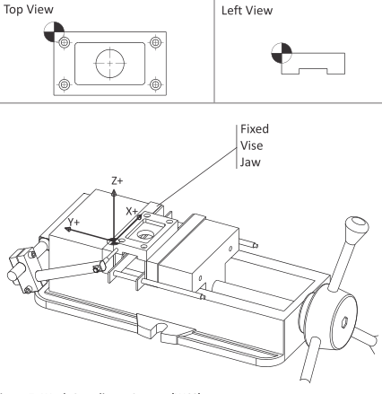
Figure 7: Work Coordinate System (WCS)
WCS Example
The following example shows why and how the WCS is set up a typical part that is machined on multiple sides by gripping in a vise. This is one of the most common ways to hold a part. Pay particular attention how the part is rotated between jobs.
The term, Job, means a unique machining setup on the machine. For example, a part that requires the part to be moved or rotated three times on the CNC is said to be composed of three jobs; one for each setup.
WCSExample - Job 1
Figure 12 shows a part gripped in a six inch wide precision CNC vise. The outside shape of this part was machined to size on a manual mill before being set on the CNC machine. The CNC is used to create the holes, pockets, and slot on this block.
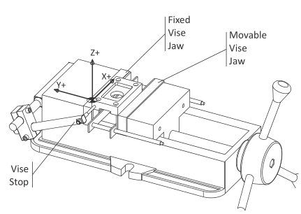
Figure 12: Tool Length Offset Example (Job 1)
Before clamping the part, the vise is aligned and bolted to the machine table. This assures the part WCS X−axis is aligned with the machine X−axis.
Parallels (precision ground rails) are used to support the part. These ensure the XY−Plane of the part is parallel to the machine table XY−Plane.
The left face of the part rests against a Vise Stop. The Vise Stop establishes the X−axis origin. As new parts are loaded into the vise, the operator slides them against the vise stop. This ensures all parts are loaded into the exact same position each time.
Because the edges of the block are already milled, the WCS XY location is easily found using an Edge Finder (Lesson 6, Set Fixture Offset XY) or part probe.
The vise has two jaws; a fixed back jaw a front jaw that can close and open to grip or release the part. Because the location of the moving jaw varies depending how much force the operator uses, it is best to locate the WCS in reference to the fixed jaw. The fixed jaw position is not significantly affected by clamping force.
Notice that, because the fixed vise jaw does not move regardless of how tightly the vise is closed, the WCS Y− origin does not change. In other words, the Y−origin is repeatable. The concept of repeatability is essential to precision machining. If the datum shifts for any reason, it is impossible to make any two parts exactly alike.
WCS Example – Job 2
After the pocket, holes, and through round hole are machined on the first side of the part, the part is flipped over in the vise to create the slot. Whether a new WCS must be defined, and how the part is flipped, depends on the part geometry and type of setup.
As shown in Figure 13, because the outside dimensions of the part were established prior to machining, and because the part is flipped 180 degrees, the location of the WCS does not change. Therefore, there is no need to define a new WCS to machine the slot. Fixture Offset G54 can be used to machine both sides.
However, how the part is turned over does matter because of how a vise works. As mentioned earlier, a vise exerts a tremendous amount of clamping force (up to 6,000 lbs or more) and so the actual position of the moving vise jaw depends on how tightly the vise is closed.
This variability is so large that it is common practice to mark the closed position of the handle with a black marker or use a torque wrench to ensure the clamping pressure is consistent between parts. Vise force can even significantly deform thin parts if excessive force is applied.
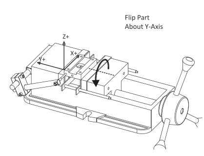
Figure 13: WCS (Job 2)
By flipping the part about the Y−axis, the same edge of the part (XZ Plane) rests against the fixed jaw. Since this position does change based on clamping force, and because the vise stop is also unaffected by clamping force, the WCS for Job 2 is also repeatable.
WCS Example – Job 3
Drilling the hole in the side of the part means turning it again to stand on end, as shown in Figure 14. Again, rotate the part about the Y−axis so that the Y−origin of the WCS (XZ reference) plane does not shift or change based on clamping force.
Notice that the WCS used in Job 1 and 2 cannot be used because the part standing on end is much taller. A new Fixture Offset is defined (G55) to shift the datum to the point shown.
It is also worth noticing that, in order to increase gripping surface, the parallels have been removed. The vise stop has also been lowered so the stylus contacts the face of the part, not the bottom of the pocket.
The best practice is to maintain as many reference surfaces as possible whenever the part is rotated. By turning the part as shown in Figure 14, two of the reference planes are used. This helps ensure the hole will be located precisely on the part side.
As a practical matter, the machinist could set up a second vise on the machine for this operation. If making many parts without a second vise, they might choose to machine the top and bottom of all parts, then reconfigure the vise as shown and make the hole in all parts.
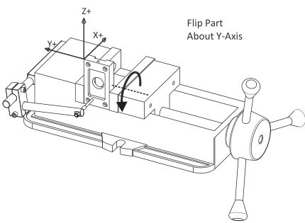
Figure 14: WCS (Job 3)
4.4 Machine and Tool Offsets
Machine Offsets
Because it is difficult to place a vise in the exact same position on the machine each time, the distance from Home to the WCS is usually not known until the vise is set and aligned with the machine. Machine set up is best done after the program is completely written, because it is expensive to keep a CNC machine idle waiting for the CNC programming to be done. Besides, the programmer may change their mind during the CAM process, rendering any pre−planned setup obsolete.
To complicate matters further, different tools extend out from the machine spindle different lengths, also a value difficult to determine in advance. For example, a long end mill extends further from the spindle face than a stub length drill. If the tool wears or breaks and must be replaced, it is almost impossible to set it the exact length out of the tool holder each time.
جهت خرید قطعات سی ان سی و اطلاع از قیمت های لوازم cnc اینجا کلیک کنید.
Therefore, there must be some way to relate the Machine Coordinate system to the part WCS and take into account varying tool lengths. This is done using machine Tool and Fixture Offsets. There are many offsets available on CNC machines. Understanding how they work and to correctly use them together is essential for successful CNC machining.
Fixture Offset XY
As long as the part is positioned where the tool can reach all machining operations it can be located anywhere in the machine envelope. Once the Fixture Offset values are found, entered into the control, and activated by the CNC program, the CNC control works behind the scene to translate program coordinates to WCS coordinates.
Notice in Figure 8 how Fixture Offsets (+X, −Y) are used to shift the centerline of the machine spindle directly over the WCS.
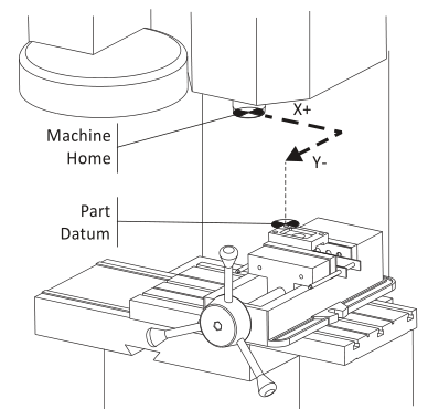
Figure 8: Fixture Offset Shifts Machine to WCS
Fixture Offset Z
The Fixture Offset Z value is combined with the Tool Length offset to indicate to the machine how to shift the Z− datum from part home to the part Z−zero, taking into account the length of the tool. Fixture Offset Z may or may not be used, depending on how the machine is set up and operated.
Lesson 6 (CNC Operation) and Appendix B (Alternate Tool Setting Methods) describe the various ways that these two values can be used. Follow the procedure in use at your facility or refer to your machine tool documentation to determine which method to use.
Tool Length Offset (TLO)
Every tool loaded into the machine is a different length. In fact, if a tool is replaced due to wear or breaking, the length of its replacement will likely change because it is almost impossible to set a new tool in the holder in exactly the same place as the old one. The CNC machine needs some way of knowing how far each tool extends from the spindle to the tip. This is accomplished using a Tool Length Offset (TLO).
In its simplest use, the TLO is found by jogging the spindle with tool from the machine home Z−position to the part Z−zero position, as shown on the far left in Figure 9 below. The tool is jogged to the part datum Z and the distance travelled is measured. This value is entered in the TLO register for that tool. Problems with this method include the need to face mill the part to the correct depth before setting tools. Also, if the Z−datum is cut away (typical of 3D surfaced parts) it is impossible to set the datum should a tool break or wear and need to be replaced. All tools must be reset whenever a new job is set up. When this method is used, the Fixture Offset Z is not used, but set to zero.
The method shown in the center is much better and used in this book. All tools are set to a known Z−position, such the top of a precision 1−2−3 block resting on the machine table. This makes it very easy to reset tools if worn or broken.
A tool probe is very similar to the 1−2−3 block method, except the machine uses a special cycle to automatically find the TLO. It does this slowly lowering the tool until the tip touches the probe and then updates the TLO register. This method is fast, safe and accurate but requires the machine be equipped with a tool probe. Also, tool probes are expensive so care must be taken to never crash the tool into the probe.
Both the 2nd and 3rd methods also require the distance from the tool setting position (the top of the 1−2−3 block or tool probe) to the part datum to be found and entered in the Fixture Offset Z. The machine adds the two values together to determine the total tool length offset. A method for doing this is included in Lesson 6.
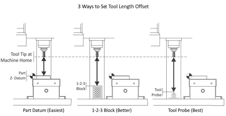
Figure 9: Ways to Set TLO