 فارسی
فارسی  English
 Upon successful completion of this lesson, you will be able to:
- Define CNC
- List the sequence of operations in a typical CNC
- List the most commonly used G−codes, their meaning, and syntax.
- List the most commonly used M−codes, their meaning, and syntax.
- List the most commonly used special characters in a CNC Program and their
- Describe the organization, motion, and actions in a simple CNC program.
Overview
CNC machines are very accurate and powerful industrial robots developed jointly by Mr. John Parsons, IBM and Massachusetts Institute of Technology Servomechanism Laboratory in the 1950’s.
Most CNC machine tools use a language set by the Electronics Industry Association (EIA) in the 1960’s. The official name of this language is RS−274D, but everyone refers it “G−code” or “G&M Code” because many of the words of this language begin with the letters G or M.
While many of the words used by different CNC machines are the same, there are differences between makes and models. This is due in part to machines having different configurations and options. For example, a machine with a chip conveyor will have words to turn the conveyor on and off, while a machine without a conveyor does not. So, while RS−274D is a standard, it is not rigid or enforced. Always refer to the machine documentation for the exact words and syntax for your CNC machine.
جهت خرید قطعات سی ان سی و اطلاع از قیمت های لوازم cnc اینجا کلیک کنید.
Most machines have a vocabulary of at least a hundred words, but only about thirty that are used often. These thirty or so words are best memorized because they appear in almost every CNC program and knowing them helps you work more efficiently.
The G−code language was developed when machine controls had very little memory. It was therefore designed to be as compact as possible. While at first this language may seem arcane, the modern machine tool language is the safest and most efficient way yet devised to control machine tool motion. G&M codes, along with coordinates and other parameters, comprise what is called a CNC program.
5.1 CNC Language and Structure
CNC programs list instructions to be performed in the order they are written. They read like a book, left to right and top−down. Each sentence in a CNC program is written on a separate line, called a Block. Blocks are arranged in a specific sequence that promotes safety, predictability and readability, so it is important to adhere to a standard program structure.
Typically, blocks are arranged in the following order:
- Program Start
- Load Tool
- Spindle On
- Coolant On
- Rapid to position above part
- Machining operation
- Coolant Off
- Spindle Off
- Move to safe position
- End program
The steps listed above represent the simplest type of CNC program, where only one tool is used and one operation performed. Programs that use multiple tools repeat steps two through nine for each.
Table 1 and Table 2 on the next pages show the most common G and M codes that should be memorized if possible.
Like any language, the G−code language has rules. For example, some codes are modal, meaning they do not have to be repeated if they do not change between blocks. Some codes have different meanings depending on how and where there are used.
While these rules are covered in this chapter, do not concern yourself with learning every nuance of the language. It is the job of the job of the CADƒCAM software Post Processor to properly format and write the CNC program.
Program Format
The program in Figure 1 below machines a square contour and drills a hole.
|
Block |
Description |
Purpose |
|
% O0001 (PROJECT1) (T1 0.25 END MILL) N1 G17 G20 G40 G49 G80 G90 |
Start of program. Program number (Program Name). Tool description for operator. Safety block to ensure machine is in safe mode. |
Start Program |
|
N2T1 M6 N3 S9200 M3 |
Load Tool #1. Spindle Speed 9200 RPM, On CW. |
Change Tool |
|
N4 G54 N5 M8 N6 GOO X-0.025 Y-0.275 N7 G43 Zl. Hl N8 ZO.l N9 G01 Z-O.l F18. |
Use Fixture Offset #1. Coolant On. Rapid above part. Rapid to safe plane, use Tool Length Offset #1. Rapid to feed plane. Line move to cutting depth at 18 IPM. |
Move To Position |
|
N10 G41 YO.l DI F36. Nil Y2.025 N12 X2.025 N13 Y-0.025 N14 X-0.025 N15 G40 X-0.4 N16 G00Z1. |
CDC Left, Lead in line, Dia. Offset #1, 36 IPM. Line move. Line move. Line move. Line move. Turn CDC off with lead−out move. Rapid to safe plane. |
Machine Contour |
|
N17 M5 N18 M9 (T2 0.25 DRILL) N19 T2 M6 N20S3820M3 |
Spindle Off. Coolant Off. Tool description for operator. Load Tool #2. Spindle Speed 3820 RPM, On CW. |
Change Tool |
|
N21 M8 N22 XI. Yl. N23 G43 Zl. H2 N24 Z0.25 |
Coolant On. Rapid above hole. Rapid to safe plane, use Tool Length Offset 2. Rapid to feed plane.
|
Move To Position |
|
N25 G98 G81 Z-0.325 RO.l F12. N26 G80 N27 Zl. |
Drill hole (canned) cycle, Depth Z−.325, F12. Cancel drill cycle. Rapid to safe plane. |
Drill Hole |
|
N28 M5 N29 M9 N30 G91 G28 ZO N31 G91 G28 XO YO N32 G90 N33 M30 % |
Spindle Off. Coolant Off. Return to machine Home position in Z. Return to machine Home position in XY. Reset to absolute positioning mode (for safety). Reset program to beginning. End Program. |
End Program |
Figure 1: Simple CNC Program
5.2 CNC Editor
CNC programs are simple ASCII character text files that can be viewed or edited in any text editor. Refer to the HSMWorks Editor Help files for specific instructions on how to use the Editor.
5.3 Alphabetic & Special Character Address Codes
Every letter of the alphabet is used as a machine address code. In fact, some are used more than once, and their meaning changes based on which G−code appears in the same block.
Codes are either modal, which means they remain in effect until cancelled or changed, or non−modal, which means they are effective only in the current block.
The table below lists the most common address codes. A complete list is included in Appendix B, G−M Code Reference.
|
Code |
Meaning |
|
A |
Rotation about X−axis. |
|
B |
Rotation about Y−axis. |
|
C |
Rotation about Z−axis. |
|
D |
Cutter diameter compensation (CDC) offset address. |
|
F |
Feed rate. |
|
G |
G−Code (preparatory code). |
|
H |
Tool length offset (TLO). |
|
1 |
Arc center X−vector, also used in drill cycles. |
|
J |
Arc center Y−vector, also used in drill cycles. |
|
K |
Arc center Z−vector, also used in drill cycles. |
|
M |
M−Code (miscellaneous code). |
|
N |
Block Number. |
|
O |
Program Number. |
|
P |
Dwell time. |
|
Q |
Used in drill cycles. |
|
R |
Arc radius, also used in drill cycles. |
|
S |
Spindle speed in RPM. |
|
T |
Tool number. |
|
X |
X−coordinate. |
|
Y |
Y−coordinate. |
|
Z |
Z−coordinate. |
Table 3: Common Alphanumeric Address Codes
Alphabetic Address Code Definitions
Here are the most common alphabetic address code definitions, examples and restrictions of use. Most modern machines use these codes.
A، B، C 4th/5th Axis Rotary Motion
Rotation about the X, Y or Z−axis respectively. The angle is in degrees and up to three decimal places precision.
G1 A30.513 B90.
D Tool Diameter Register
Used to compensate for tool diameter wear and deflection. D is accompanied by an integer that is the same as the tool number (T1 uses D1, etc). No decimal point is used. It is always used in conjunction with G41 or G42 and a XY move (never an arc). When called, the control reads the register and offsets the tool path left (G41) or right (G42) by the value in the register.
G1 G41 XI. DI
F Feed Rate
Sets the feed rate when machining lines, arcs or drill cycles. Feed rate can be in Inches per Minute (G94 mode) or Inverse Time (G93 mode). Feed rates can be up to three decimal places accuracy (for tap cycles) and require a decimal point.
G1 XI. YO. F18.
G Preparatory Code
Always accompanied by an integer that determines its meaning. Most G−codes are modal. Expanded definitions of G− codes appear in the next section of this chapter.
G2X1. YI. 1.25 JO.
H Tool Length Compensation Register
This code calls a tool length offset (TLO) register on the control. The control combines the TLO and Fixture Offset Z values to know where the tool is in relation to the part datum. It is always accompanied by an integer (H1, H2, etc), G43, and Z coordinate.
G43 H1Z1.
I Arc Center or Drill Cycle Data
For arc moves (G2ƒG3), this is the incremental X−distance from the arc start point to the arc center. Certain drill cycles also use I as an optional parameter.
G2X.1Y2.025 10. JO.125
J Arc Center or Drill Cycle Data
For arc moves (G2ƒG3), this is the incremental Y−distance from the arc start point to the arc center. Certain drill cycles also use J as an optional parameter.
G2 X.1 Y2.025 I0. J0.125
K Arc Center or Drill Cycle Data
For an arc move (G2ƒG3) this is the incremental Z−distance from the arc start point to the arc center. In the G17 plane, this is the incremental Z−distance for helical moves. Certain drill cycles also use J as an optional parameter.
G18 G3 X.1 Z2.025 I0. K0.125
M Preparatory Code
Always accompanied by an integer that determines its meaning. Only one M−code is allowed in each block of code. Expanded definitions of M−codes appear later in this chapter.
M8
N Block Number
Block numbers can make the CNC program easier to read. They are seldom required for CADƒCAM generated programs with no subprograms. Because they take up control memory most 3D programs do not use block numbers. Block numbers are integers up to five characters long with no decimal point. They cannot appear before the tape startƒend character (%) and usually do not appear before a comment only block.
N100 T2 M6
O Program Number
Programs are stored on the control by their program number. This is an integer that is preceded by the letter O and has no decimal places.
00002 (PROJECT 1)
P Delay
Dwell (delay) in seconds. Accompanied by G4 unless used within certain drill cycles.
G4 P.1
Q Drill Cycle Optional Data
The incremental feed distance per pass in a peck drill cycle.
G83 X1. Y1. Z-.5 F12. R.1 Q.1 P5.
R Arc Radius or Drill Cycle Optional Data
Arcs can be defined using the arc radius R or I,J,K vectors. IJK’s are more reliable than R’s so it is recommended to use them instead. R is also used by drill cycles as the return plane Z value.
G83 Z-.5 F12. R.1 Q.1 P5.
S Spindle Speed
Spindle speed in revolutions per minute (RPM). It is an integer value with no decimal, and always used in conjunction with M3 (Spindle on CW) or M4 (Spindle on CCW).
S3820 M3
T Tool number
Selects tool. It is an integer value always accompanied by M6 (tool change code).
T1 M6
X X-Coordinate
Coordinate data for the X−axis. Up to four places after the decimal are allowed and trailing zeros are not used. Coordinates are modal, so there is no need to repeat them in subsequent blocks if they do not change.
G1 X1. 1252
Y Y-Coordinate
Coordinate data for the Y−axis.
G1 Y1.
Z Z-Coordinate
Coordinate data for the Z−axis.
G1 Z-.125
Special Character Code Definitions
The following is a list of commonly used special characters, their meaning, use, and restrictions.
% Program Start or End
All programs begin and end with % on a block by itself. This code is called tape rewind character (a holdover from the days when programs were loaded using paper tapes).
() Comments
Comments to the operator must be all caps and enclosed within brackets. The maximum length of a comment is 40 characters and all characters are capitalized.
(T2: .375 END MILL)
/ Block Delete
Codes after this character are ignored if the Block Delete switch on the control is on.
/M0
; End of Block
This character is not visible when the CNC program is read in a text editor (carriage return), but does appear at the end of every block of code when the program is displayed on the machine control.
N8 Z0.1;
| code |
Meaning |
|
G0 |
Rapid motion. Used to position the machine for non−milling moves. |
|
G1 |
Line motion at a specified feed rate. |
|
G2 |
Clockwise arc. |
|
G3 |
Counterclockwise arc. |
|
G4 |
Dwell. |
|
G28 |
Return to machine home position. |
|
G40 |
Cutter Diameter Compensation (CDC) off. |
|
G41 |
Cutter Diameter Compensation (CDC) left. |
|
G42 |
Cutter Diameter Compensation (CDC) right. |
|
G43 |
Tool length offset (TLO). |
|
G54 |
Fixture Offset #1. |
|
G55 |
Fixture Offset #2. |
|
G56 |
Fixture Offset #3. |
|
G57 |
Fixture Offset #4. |
|
G58 |
Fixture Offset #5. |
|
G59 |
Fixture Offset #6. |
|
G80 |
Cancel drill cycle. |
|
G81 |
Simple drill cycle. |
|
G82 |
Simple drill cycle with dwell. |
|
G83 |
Peck drill cycle. |
|
G84 |
Tap cycle. |
|
G90 |
Absolute coordinate programming mode. |
|
G91 |
Incremental coordinate programming mode. |
|
G98 |
Drill cycle return to Initial point (R). |
|
G99 |
Drill cycle return to Reference plane (last Z Height) |
Table 1: Common G-Codes
5.4 کدهای G&M
G&M Codes make up the most of the contents of the CNC program. The definition of each class of code and specific meanings of the most important codes are covered next.
G-Codes
Codes that begin with G are called preparatory words because they prepare the machine for a certain type of motion. The most common G−codes are shown in Table 1 and a complete list and their meaning is included in Appendix B, G−M Code Reference.
M-Codes
Codes that begin with M are called miscellaneous words. They control machine auxiliary options like coolant and spindle direction. Only one M−code can appear in each block of code.
The table below lists the most common M codes and their meaning. A complete list of M−codes is included in Appendix B, G−M Code Reference.
|
Code |
Meaning |
|
M0 |
Program stop. Press Cycle Start button to continue. |
|
M1 |
Optional stop. Only executed if Op Stop switch on the CNC control is turned ON. |
|
M2 |
End of program. |
|
M3 |
Spindle on Clockwise. |
|
M4 |
Spindle on Counterclockwise. |
|
M5 |
Spindle stop. |
|
M6 |
Change tool. |
|
M8 |
Coolant on. |
|
M9 |
Coolant off. |
|
M30 |
End program and press Cycle Start to run it again. |
Table 2: Common M-Codes
5.5 Select G-Code Definitions (Expanded)
G0 Rapid Move
This code commands the machine to move as fast as it can to a specified point. It is always used with a coordinate position and is modal. Unlike G1, G0 does not coordinate the axes to move in a straight line. Rather, each axis moves at its maximum speed until it is satisfied. This results in “dogleg” motion as shown in Figure 2, below.
G0 X0. Y0.
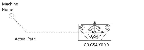
Figure 2: G0 Dogleg Motion
G1 Linear Move
This command moves the tool in a straight line at a programmed feed rate.
G1 X1. Y1.1255 F32.
G2/G3 CW/CCW Arc
G2 commands clockwise arcs. G3 commands counterclockwise arcs. Arcs must exist on a plane (G17ƒG18ƒG19) and include the coordinates of the arc end point and IJK vectors indicating the arc center location.
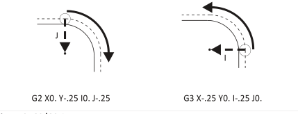
Figure 3: G2/G3 Arcs
G17/G18/G19 Plane Designation
Arcs must exist on a plane designated by the command G17 (XY), G18 (XZ) or G19 (YZ). G17 is the machine default.
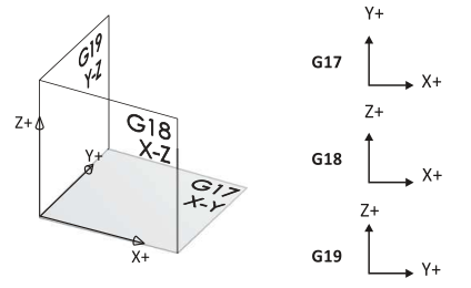
Figure 4: Plane Designations
G40/G41/G42 Cutter Diameter Compensation (CDC)
CDC is a key to precision CNC machining, allowing the operator to compensate for tool wear and deflection by commanding the machine to veer left (G41) or right (G42) from the programmed path. G40 cancels cutter compensation. The amount of offset is entered in a CNC control D−register. The wear register can be thought of like a table that the control refers to with every move.
|
Tool Diameter Offset |
value |
|
D1 |
0.0020 |
|
D2 |
0.0000 |
|
D3 |
0.0000 |
|
D4 |
0.0000 |
|
D5 |
0.0000 |
|
D6 |
0.0000 |
Figure 5: Diameter Offset Register
The value in the D−register is calculated by the machine tool operator, who monitors the finished size of part features, compares them with the print, and enters the difference in the register as needed to keep the part within specifications. If there is no deviation, the register is set to zero.
G1 G41 D1 X1.0 Y.25 F36.
G43 Tool Length Compensation
G43 activates tool length compensation. It is always accompanied by an H−code and Z−move, where H is the tool length offset (TLO) register to read, and Z is the height to go to in reference to the part datum.
The (TLO) can be thought of like a table on the control:
|
Tool Length Resister |
Z |
|
H1 |
12.6280 |
|
H2 |
6.3582 |
|
H3 |
9.7852 |
|
H4 |
6.8943 |
|
H5 |
10.5673 |
|
H6 |
7.1258 |
جدول 5- Work Offsets
The TLO is combined with the active fixture offset on the control so the machine knows where the tip of the tool is in relation to the part datum. The process for finding the TLO detailed in Lesson 6, CNC Operation.
G43 H1 Z1
G54 Work Offset
Work offsets are data registers in the CNC control that hold the distance from the machine home X, Y, Z position to the part datum. These offsets can be thought of like a table on the control:
|
Work Offset |
X |
Y |
z |
|
G54 |
14.2567 |
6.6597 |
2.0183 |
|
G55 |
0.0000 |
0.0000 |
0.0000 |
|
G56 |
0.0000 |
0.0000 |
0.0000 |
|
G57 |
0.0000 |
0.0000 |
0.0000 |
|
G58 |
0.0000 |
0.0000 |
0.0000 |
|
G59 |
0.0000 |
0.0000 |
0.0000 |
Figure 7: Work Offsets
The X and Y values represent the distance from the machine home to part datum XY. The Z value is the distance from the tool reference point (for example, the top of a 1−2−3 block) and the part Z−datum. The process for finding TLO and fixture offset Z is detailed in Lesson 6, CNC Operation.
G54 X0. Y0.
5.6 Canned Cycles
Canned cycles are special codes that act like a macro. They are used for hole making and allow one compact block of code to command many moves. For example, a hole can be created using a peck drill cycle with two lines of code (left column) whereas the same move would require maybe twenty or more lines of code if each motion was commanded separately (right column).
|
Canned Cycle |
Equivalent Motion: Expanded Code |
|
N70 G98 G83 XI. Y1. Z-1.04 R0.06 Q0.15 PO F9. N75 G80 |
N70 Z0.06 N75 Z0.04 N80G01Z-0.19 F9. N85 G00Z0.06 N90 Z-0.11 N95 G01Z-0.34 N100 GOO Z0.06 N105 Z-0.26 N110 G01Z-0.49. N115 GOO Z0.06 N120 Z-0.41 N125 G01Z-0.64. N130 GOO Z0.06 N135 Z-0.56 N140 G01Z-0.79 N145 GOO Z0.06 N150Z-0.71 N155 G01Z-0.94. N160 GOO Z0.06 N165 Z-0.86 N170 GO1 Z-1.04. N175 GOO Z0.25 |
Figure 8: Canned Cycle vs. Expanded Code
G81 Simple Drill Cycle
This cycle makes holes by feeding to depth at a programmed feed rate and then retracting at rapid rate. It is accompanied by G98 or G99, XYZ coordinates, feed rate, and R. R is the feed plane and Z is final depth of the tool tip.
جهت خرید قطعات سی ان سی و اطلاع از قیمت های لوازم cnc اینجا کلیک کنید.
All drill cycles are accompanied by G98 or G99 that determine how high the tool retracts between holes.
G0 Z1. G43 H1
G98 G81 X.5 Y.5 Z-1. R.1 F9.5
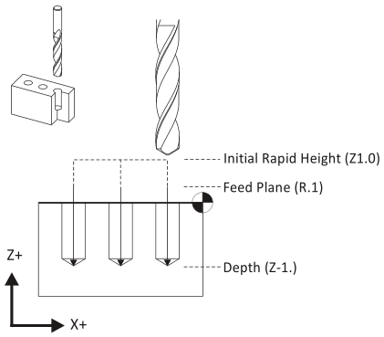
Figure 9: G81 Simple Drill Cycle
G82 Spot Drill Cycle
This cycle is identical to G81 except it includes a dwell value, P (in seconds). P is used to pause the tool feed rate at the final depth to create a clean countersink or counterbore finish.
G0 Z1. G43 H1
G98 G82 X.5 Y.5 Z-.0925 P.1 R0.1 F9.5
G83 Peck Drill
A peck drill cycle is used on deep holes. The tool drills an incremental distance (Q) and then fully retracts from the hole. This breaks the chip, clears material out of the hole, and allows coolant to cool the drill and flush out the hole, reducing the chance of the tool breaking and producing a better quality hole. The simplest form of this cycle is shown in Figure 8. Another version of this cycle, called a "deep drill cycle", uses I,J,K parameters to reduce the amount of peck as the hole gets deeper.
G0 Z1. G43 H1
G83 X.5 Y.5 Z-1. R0.1 Q.25 F9.
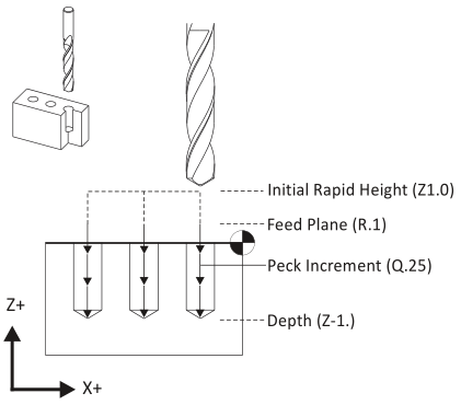
Figure 10: G83 Peck Drill Cycle
G84 Tap Cycle
This code commands the machine to interpret coordinates as absolute position moves in the active Work Coordinate System. All programs are written in absolute coordinates.
G0 Z1. G43 H1
G84 X.5 Y.5 Z-1.5 R0.1 F20.
G90 Absolute Positioning
This code commands the machine to interpret coordinates as absolute position moves in the active Work Coordinate System. All programs are written in absolute coordinates.
G90 G0 X1. Y1.
G91 Incremental Positioning
This code commands the machine to interpret coordinates as incremental position moves. G91 is used by subprograms but most programming done with CADƒCAM software and does not use subprograms.
The only common use of G91 is in combination with G28 to send the machine back to its home position at the end of the program. The machine must be set back to G90 mode in the next block as a safety measure.
G91 G28 Z0.
G98 Return to Initial Rapid Height
This code is used in drill cycles to retract the tool to the clearance plane (set in the next previous block) between holes to avoid clamps.
G0 Z1. G43 H1
G98 G81 Z-0.325 R0.1 F12
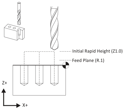
Figure 11: G98 (Return to Clearance Plane)
G99 Return to R-Plane
This code is used in drill cycles to retract the tool to the rapid plane (R) between holes. G99 mode is the machine default and is used when clamp clearance between holes is not an issue.
G0 Z1. G43 H1
G99 G81 Z-0.325 R0.1 F12
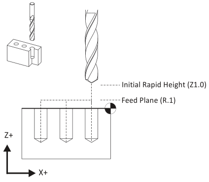
Figure 12: G99 Motion (Return to R-Plane)