 فارسی
فارسی  English
 Upon successful completion of this lesson, you will be able to:
- Explain the difference between 2−1/2D, 3D, and 4−axis machined parts.
- Explain the difference between common CAD and CAM graphics views
- Identify 2D machining features based on part geometry and your knowledge of tools and 2D
- Identify commonly used machining parameters for 2D tool path
- Explain the purpose, general parameters, and use of facing
- Explain the purpose, general parameters, and use of 2D contour
- Explain the purpose and rules for using Cutter Diameter Compensation (CDC).
- Explain the purpose, general parameters, and use of pocketing
- Explain the rules for slot milling
- Explain the rules for chamfer milling
- Explain the rules for radius milling
- Explain the rules for drilling and peck drilling
- Explain the rules for tapping toolpaths.
Overview
CNC milling toolpaths are broadly classified as either 2D, 3D, 4−axis, and 5−axis, depending on the number of axes involved and how they move. The term, 2D, is a bit of a misnomer because all modern CNC machines control at least three axis and all three axes move at one time or another for every 2D machining operation. A more accurate term, 2−1/2D, is commonly used in CNC manufacturing.
7.1 2D/3D/4X/5X Defined
2D (Prismatic) Parts
2−1/2D milling toolpaths machine only in the XY plane. The Z axis is used only to position the tool at depth. The move to the cutting plane is a straight down feed, rapid, ramp or helical feed move.
The term, Prismatic, is a term commonly used in engineering used to describe 2−1/2D parts. There are, however, prismatic parts that require 4th or 5−Axis machining, so the term is used in machining only to describe parts where all machined faces lie normal to the machine tool spindle. Because 2−1ƒ2D is a clumsy term this book uses Prismatic and 2D interchangeably to describe parts just described, on a CNC mill with three controllable axes (XYZ). The XY axes are normal to the machine spindle and Z is used only to position the tool to depth (either in a feed or rapid motion).
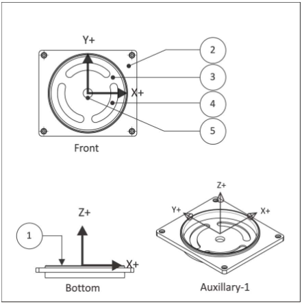
Figure 1: Prismatic Part (Orientation in CAD)
Figure 1 shows a prismatic part. All machined features lie parallel to the XY plane. Each Z−level can be machined by positiong the tool at a fixed Z−level and then moving the XY axes to remove material. machining. Every feature can be reached with the tool approaching either from the Front or Bottom views. There are several cutting planes in this example, including the model top (1), top of the face where the holes start (2), the bottom of the pocket (3) where the slots begin, the bottom of the slots (4), and the bottom of the hole through the center (5).
3D Parts
3D refers to non−prismatic parts, including molds and complex organic shapes. Most consumer goods, for example, include 3D features. Figure 3 shows half of a stamping die. This part is typical in that it includes both 3D and 2D features. The 2D features are the top face (1) , and the outside contour (2).
جهت خرید قطعات سی ان سی و اطلاع از قیمت های لوازم cnc اینجا کلیک کنید.
3D features, like the revolved surfaces (3) and fillet (4), require more complex machine motion. The revolved surfaces require XZ tool motion. The fillet requires XYZ tool motion. Even the flat (5) and cavity roughing (though technically planar) require 3D toolpaths because the adjacent revolved surfaces and fillet must be considered to prevent gouging the part. The calculations required to calculate these toolpaths are highly complex and the subject of the next lesson, 3D Toolpaths (Chapter 9).
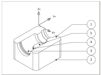
Figure 3: 3D Part
4- Axis Parts
4th axis toolpaths require an auxiliary rotary axis 4th installed on the CNC machine parallel to either the X or Y−axis. 4th axis toolpaths fall into two categories: 4th Axis Substitution and Simultaneous 4th Axis.
Axis substitution paths are illustrated in Figure 4. The most common setup is with the rotary axis mounted parallel to the CNC X−axis. With axis substitution machining, the tool axis centerline always points towards the centerline of the rotational axis (no Y−motion) when milling. The tool feeds to depth (Z) and then only up to two axes can move at once (X−A) to make the feature.
The name ‘substitution’ comes from how these paths were defined before CAD was widely used. Geometry was draw flat (XY) and then the Y−axis values were converted to A−rotational values, based on the cylinder radius. In other words, the flat geometry was “wrapped” around a constant diameter cylinder; similar to how the SolidWorks© Wrap function works.
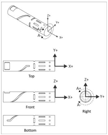
Figure 4: 4th Axis Substitution (X-A)
Simultaneous 4th axis machining allows all 4 axes to move at once (XYZA). This type of motion is very complex and is actually a sub−category of Simultaneous 5−axis machining. 5th Axis parts require all 5 machine axes to move at once (XYZAB).
Simultaneous 4th and 5th axis machining is beyond the scope of this course.
7.2 Standard CAD Views vs. CAM Views
Figure 1 shows the part oriented as it is modeled in the mechanical CAD software. For CAM, it is helpful to display the part in the same orientation as viewed while sitting on the CNC machine. For a Vertical Machining Center (VMC) this requires updating standard views to look like those shown in Figure 2. The G− code file is generated in relation to the Work Coordinate System (WCS), so changing views is not required for CNC programming. It simply helps visualize CNC machining processes when using CAM.
In SolidWorks to switch views from CAD space (Figure 1) to CAM space (Figure 2) to the following:
- Open the View Orientation dialog and select Front (view) so the part displays as shown in Figure
- Highlight the option
- Select Update Standard Views.
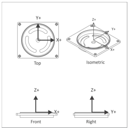
Figure 2: Prismatic Part (Orientation in CAM)
7.3 CAD Features vs. Machining Features
Parts designed in SolidWorks© are composed of features, including Extruded Cuts, Fillets, Chamfers, and Holes. A CNC milling machine creates these features using machining operations like Face, 2D Contour, 2D Pocket, and various Drilling operations.
Knowing which machining operation to use to make which feature is sometimes obvious. For example, the slots in Figure 3 are created using a Slot Mill pocketing operation, the large extruded cut using 2D Pocket, and the Chamfer using Chamfer milling.
However, sometimes these decisions are not so obvious. For example, the hole through the part center could be created using Drill, 2D Contour, 2D Pocket or Circular Pocket milling. You may wonder, is the large flat (where the holes begin) a 2D Contour or 2D Pocket? Furthermore, which features on this part should be machined from the Top and which from the bottom?
The operations the CNC programmer chooses and their sequence depends on a bewildering number of factors, including feature size, tool used, capabilities of the machine, feature tolerance and how the part is gripped. The rest of this chapter will introduce how to begin looking at 2D parts and begin making CNC process decisions.
To begin with, in most cases you want to first machine the side of a 2D part that has the most features; finishing as much of the part as possible with the first CNC setup. This is often the Front view of a part designed in SolidWorks. In this example, that means machining the side with the slots first (Front CAD view) rather than the opposite side.
7.4 Toolpaths By Type and Use
Before going further, it is helpful to understand how 2D toolpaths are classified in most CAM software. Table 1 lists the common 2D toolpaths by type and common use. For example, 2D contour, chamfer, and fillet toolpaths are often accomplished using the 2D Contour menu selection. Of course, where each function is located will be slightly different depending on the CAM product, but this list is appropriate to most modern CAM.
|
Type |
Toolpath |
Common Uses |
|
Face |
Face |
|
|
Island Facing |
|
|
|
2D Contour |
Contour |
|
|
chamfer |
|
|
|
fillet |
|
|
|
|
|
|
|
Slot Mill |
|
|
|
Drill |
Drill |
|
|
Circular Pocket Milling |
|
|
|
Thread Mill |
|
Table 1: 2D Toolpaths and Common Uses
It is probably obvious to you now that manufacturing is an exceedingly complex process. Many factors influence every decision and often more than one solution to any problem. Manufacturing is also a winƒlose game. Either the part is right (within tolerance) or not. Don’t be overwhelmed by the choices for now. Some knowledge and experience will help you settle many of these variables and greatly simplify the job of planning CNC processes.
7.5 2D Machining Features Example
Figure 5 and Table 2 shows the operations and machining sequence to CNC mill this part.
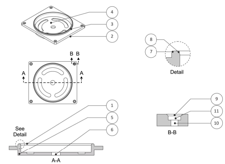
Figure 3: 2D Machining Features Example
|
Op |
Toolpath |
Notes |
|
1 |
Face |
It is common practice that the first machining operation roughs and finishes to the highest flat surface of the part. Face paths overlap the sides of the loop selected. |
|
2 |
2D Contour |
Machine outside loop. |
|
3 |
2D Contour |
Machine outside of boss. |
|
4 |
2D Pocket |
Use Pocket to rough and finish enclosed loops. |
|
5 |
Slot Mill |
Mill slots. |
|
6 |
Circular Pocket Mill |
Machine the center hole through. You could also use a Drill operation to make this hole, but would center−drill the hole first. |
|
7 |
Chamfer |
Use 2D Contour, Chamfer function and a chamfer tool (or center drill) to make this 45 degree chamfer. |
|
8 |
Fillet |
Use 2D Contour, fillet function and a corner round tool to make this fillet feature. |
|
9 |
Spot Drill |
Spot drill all holes to:
|
|
10 |
Drill |
Drill to make hole. Do this before the Circular Pocket Mill so the Spot Drill conic still exists. |
|
11 |
Circular Pocket Mill |
Create counterbore. |
Table 2: 2D Features Example
7.6 2D Toolpath Terminology
Though the terminology and ways of working vary widely, all CAD/CAM software needs the same basic information to function. Figure 4 shows parameters common to 2D tool paths.
Figure 4: 2D Tool Path Terminology
Clearance Height is the first height the tool rapids to on its way to the start of the tool path. It is usually set 1.000in above the top of stock because this makes it easier to see if the tool length offset register was set properly.
Rapid Height is the second height the tool rapids to, and the height the tool retracts to between moves (unless set higher to clear clamps). It is usually set to .250in above the top of the finished part face.
Feed Height is the last height the tool rapids to before starting to feed into the cut. It is usually set to
.1000in above top of stock. No rapid motion occurs below this height.
Top of Stock is the top of the finished face of the part. This value is used as the reference plane for depths.
Stepdown is the depth of material removed with each cutting pass. This illustration shows one pass, but for deeper cuts or harder materials, many passes may be required to cut to the final depth.
Depth is the final cutting depth of the machining operation.
Stepover sets how much material the tool removes with each pass in the XY direction.
XY Stock Allowance is the material remaining on the finished wall of the part to be removed by subsequent operations.
Z Stock Allowance is the material remaining on the finished floor of the part to be removed by subsequent operations.
Toolpath Centerline represents the actual coordinates in the CNC program. In this book, rapid moves are shown as dashed lines and feed moves as solid.
Facing
Facing is often the first machining operation. It is used to cut away excess material and finish the highest flat face of the part. Depending on how much stock is removed, several roughing cuts may be required. A smaller finish pass ensures a flat surface and good surface finish.
Use a face mill when possible for all but the smallest part. The large diameter of facing mills and multiple carbide insert cutting edges provide for very high material removal rates.
High speed loop transitions between cut passes produce a fluid tool motion that place less stress and wear on the CNC machine.
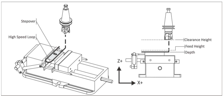
Figure 5: 2D Facing Toolpath
Rules for Facing:
- Because face mills do not plunge well, start the tool path far enough away from the part so the tool does not plunge into the stock
- Be aware that saw cut stock can vary considerably in thickness from one part to another: as much as .05in or more. When planning roughing passes, be sure to account for the worst case stock material − maximum height and add additional roughing passes as needed. It is better to have a “air cut” or two with the shortest stock than to have the tool engage too much material for the highest which could cause the tool to break or the part to be pushed out of the vise or fixture.
- Facing tool paths do not use cutter compensation (CDC).
2D Contour
Contour operations are used to rough and finish outside part walls as shown in Figure 6. Use Cutter Diameter Compensation (CDC) on high tolerance features so the tool path can be adjusted at the machine if needed to account for tool wear and deflection.
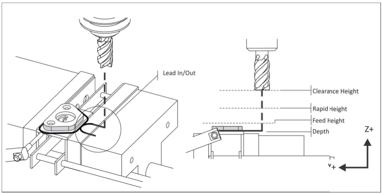
Figure 6: 2D Contour Tool Path
Rules for Contouring:
- Only use CDC when If using new tools and conservative machining parameters, features will likely be within .005 inches of the programmed path without adjustment.
- Start the tool path off the part to allow CDC to be fully in effect for the entire The combined line−arc lead−inƒout moves shown in Figure 4 work for most contours. The line is for activatingƒdeactivating compensation, and the arcs blend the path into the part wall smoothly.
- Set a rapid height value to clear all clamps or other obstacles between cuts.
- Rough the walls and leave a constant thickness of material for the finish This ensures even cutting pressure on the finish pass and thus a more accurate part.
- Extend the cut depth of full walls slightly below the bottom of the wall, but be careful not to cut into the machine table or vise hard jaws! This way, when the part if flipped over to face the other side, no flashing will be left on the bottom of the walls.
- Mill tools cut well in the XY direction, but not as well when plunging in When possible, plunge the tool away from the part to avoid Z−moves into the stock material.
- When taking multiple depths of cut, make the last pass at full depth to remove any marks left by previous depth cuts.
- For tall walls, consider taking one additional finish pass. This so−called “spring pass” follows the same path twice to ensure the walls are perfectly straight and not slightly tapered due to cutting pressure which causes the tool to bend.
Cutter Diameter Compensation
Cutter Diameter Compensation provides a way for tool paths to be adjusted at the machine to compensate for tool wear and deflection. Figure 5 shows how CDC Right (G41) causes the tool to veer to the right of the programmed path.
جهت خرید قطعات سی ان سی و اطلاع از قیمت های لوازم cnc اینجا کلیک کنید.
The compensation value is found by measuring the part feature and subtracting the actual dimension from the desired dimension. The difference is entered in the control CDC register for the tool. The next time program is run, the tool will be offset by this value.
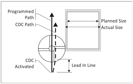
Figure 7: Cutter Diameter
CDC is activated at the end of the line on which it is called, as shown in Figure 5. Notice how the tool moves at an angle from the start to end of the lead−in line. Activate CDC while the tool is away from the part so this angle move happens away from the finished part surfaces. The line−arc moves shown in Figure 4 provide ample clearance for the tool for this purpose.
Pocketing
Pocket tool paths are used to remove excess material. An example of a spiral pocket with helical entry is shown in Figure 6. CDC is not active during the roughing cuts, but may be used for finish passes on walls.
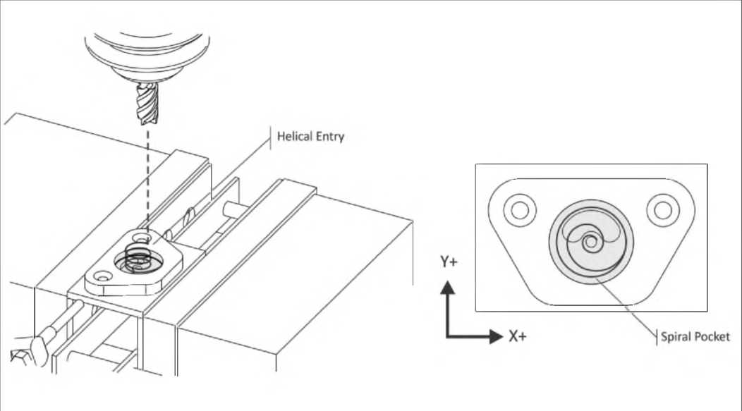
Figure 8: Pocketing
Rules for Pocketing:
- Rough passes should leave a constant thickness of material on the walls and floor of the pocket to be removed by the finish passes.
- Consider using a roughing end mill to remove most of the These serrated mills can remove material at a far faster rate than finish end mills. They do leave a poor finish on the floors and walls that must be finished with a separate finish tool and operation.
- Helical moves are a good method for entering a If space does not allow a helical entry, use a center−cutting end mill or plunge the tool through an existing hole, or a pilot hole created for this purpose. The pilot hole must be at least 50% of the tool diameter.
- Spiral pocketing paths that start near the center of the pocket and move outward in a counter−clockwise direction are best because they cause the tool to continually climb cut.
- Use CDC only on finish passes.
Slot Milling
Slots may be machined using the CADƒCAM contour, pocket, or specialized slot milling functions. In HSMWorks, use 2D pocket and select the slot geometry. HSMWorks recognizes the slot feature and applies a slot milling strategy.
Rules for Slot Milling:
- Use a tool smaller than the width of the slot whenever possible.
- A ramp plunging move as shown in Figure 7 is the most efficient way to mill a slot.
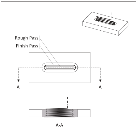
Figure 9: Slot Milling
Chamfer Milling
Chamfer is a type of 2D contour milling. Chamfer mills are of various tip angles are in high speed steel, carbide, or as insert type tools.
Rules for Chamfer Milling:
- Because the tip of a chamfer mill is not a sharp point the width of the chamfer may be wider than expected if you set the tool like an end To prevent cutting too deep, consider raising the TLO about
- .010 inches after setting Then machine the chamfer, check its size, and adjust the TLO down as needed to produce the correct width chamfer.
- Offset the chamfer mill as shown in the magnified view below to move the tool tip is away from the bottom of the This ensures a clean bottom edge and, because tool rotational velocity increases with tool diameter, is a more efficient to use the tool.
- Chamfer with a spot drill to precision de−burr sharp corners.
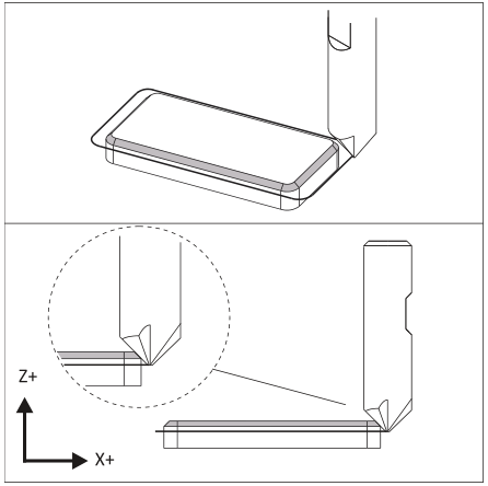
Figure 10: Chamfer Milling
Radius (Corner-Round) Milling
Radius milling is a form of contour milling. Corner round tools are available in high speed steel, carbide, or insert type tools.
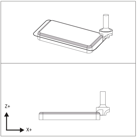
Figure 11: Radius Milling
Rules for Radius Milling:
- The horizontal and vertical cutting edges of a radius mill are sloped slightly to blend the radius into the walls.
- Take two finish passes to improve surface finish.
- Another way to form a corner radius is to use a ball mill and 3D contour tool This method saves purchasing a radius mill and is suitably efficient for prototype and small production manufacturing.
Center Drill
Center drills create a conical cut on the face of the part. This helps prevent subsequent drill tools from wobbling and thus ensures they will be positioned precisely.
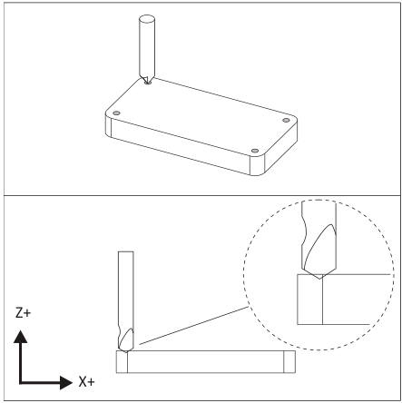
Figure 12: Center Drilling
Rules for Center Drilling:
- A good rule of thumb is to use a tip depth equal to the radius of the subsequent drill
- Use a combination center−spotting drill for spot faced holes.
Drilling
Holes that are less than the diameter of the drill can be created with a single plunge move. Deeper holes use a Peck Drill cycle where the tool is retracted after removing a small amount of material (typically .050 inches).
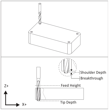
Figure 13: Drilling
Rules for Drilling:
- Center drill all holes to ensure they are located precisely.
- Peck drill (G83) holes that are deeper than the diameter of the Full retract peck drill cycles take more time than partial retracts, but minimize the chance of tool breakage.
- CNC Programs control the tip of the Be sure to provide additional depth to compensate for the tool tip and include a breakthrough allowance to prevent a flange or burr on the bottom.
Tapping
Tap cycles are similar to simple drill cycles except the feed and speed are coordinated to properly match the thread lead. CAD/CAM software calculates the feed according to the cutting speed and threads per inch (TPI) of the tap.
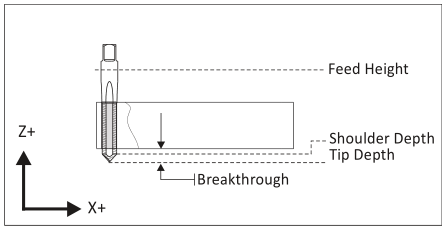
Figure 14: Tapping
Rules for Tapping:
- Use the drill chart in Appendix A to find the correct drill diameter for cutting taps. Use the manufacturers recommended drill size for form taps.
- Consider brushing on tapping fluid instead of using coolant for small tapped holes to help prevent the tap from breaking.
- Tapped holes smaller than about #8 can be difficult to create on the machine without breaking the Consider tapping these holes by hand rather than on the CNC.
- If the machine does not support Rigid Tapping, a floating tap holder is required to Refer to the tapping head documentation for proper use.
- Be sure to specify a tip depth sufficient to account for the tip and initial taper of the tap.
- Older machines may require a larger feed height to allow the machine spindle to reach full speed before the thread engages the material.