 فارسی
فارسی  English
 Upon successful completion of this lesson, you will be able to:
- Identify the elements of the Lathe coordinate
- Identify common lathe work
- List the most commonly used Lathe
- Calculate lathe speeds and
- Describe Constant Surface Speed (CSS) speed
- Explain the purpose, general parameters, and use of lathe tool paths, including face, turn, groove, cut off, thread, and drill
- Explain the purpose and general configuration of live tools.
Milling machines work by moving a spinning tool over a stationary part. Lathes work by spinning the part and moving the tool, making them ideal for round parts like shafts, pins and pulleys.
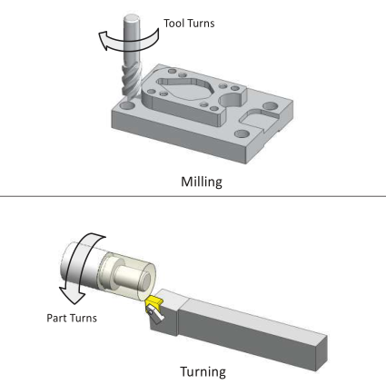
Figure 1: Milling vs. Turning
There are many different configurations of CNC lathes. Some have two spindles, some two tool turrets, and some even integrate milling or grinding in the same machine. There is also variation between similar machines. Horsepower, the size of stock that can be gripped, and how tools are held vary greatly between lathes.
جهت خرید قطعات سی ان سی و اطلاع از قیمت های لوازم cnc اینجا کلیک کنید.
Discussing every lathe configuration is beyond the scope of this book. This chapter discusses one of the most common lathe configurations, called a Turning Center, with one spindle and tool turret.
8.1 Lathe Components
The major components of a CNC turning center are shown in Figure 2.
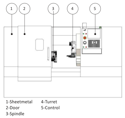
Figure 2: CNC Lathe
1- Sheetmetal
Protective housing that contain cutting chips and capture coolant for recycling.
2- Door
The door is closed during operation. Lathes can be dangerous if the part is thrown or a tool breaks during machining. The window is made from a special high impact glass. The lathe should not be operated if this glass is cracked.
3- Spindle
The spindle is attached at one end the machine drive system. The other end attaches the chuck, which grips the part.
4- Turret
The turret holds and moves the tools. Tools are bolted to the turret using a variety of specialized holders, depending on the type of tool. The turret indexes to present the tool to the work piece.
5- Control
The CNC control used to operate the machine.
Spindle
The spindle turns the chuck. The chuck grips the part using hard jaws, soft jaws, or collet. The most common configuration is the three jaw chuck, shown in Figure 3. The chuck requires air pressure to open and close the jaws, and set the gripping force. Pressure must be high enough to securely hold the part, but not so great as to deform fragile parts.
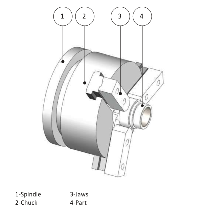
Figure 3: Spindle Detail
Turret
Tool holders bolt to either the front or perimeter of the turret. Tool changes are made by the machine indexing the turret to place the appropriate tool closest to the part.
The method by which the tools are attached to the turret, and the direction the tool faces in relation to the part, vary depending on the tool, operation, and cut direction. For example, a facing tool is oriented radially to the part, to maximize tool rigidity and work envelope. A boring bar is oriented axially to allow the bar to enter and exit the bore.
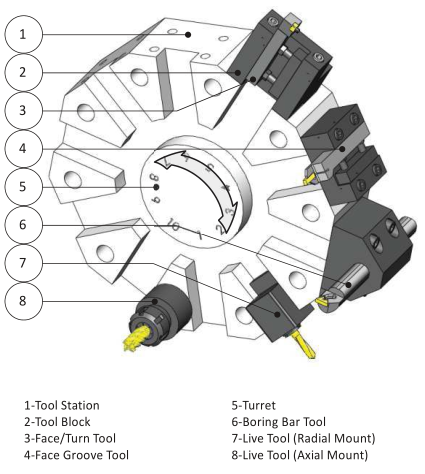
Figure 4: Turret Detail
1- Tool Station
The turret is divided into stations evenly spaced around the perimeter. Most lathes with tool turrets have about 10 tool stations. Tools are connected to the turret by a tool holder and tool block. The tool holder and block used depend on the type of tool and mount direction.
2- Tool Block
Tool blocks act as the interface between the tool holder and the turret. They bolt to the face or perimeter of the turret. Different blocks are used depending on the type of tool and orientation.
3- Turn Tool
Turning tools, which includes face, OD rough and finish, groove and cutoff, are usually mounted radially with respect to the part. The cutting tool is usually a ceramic insert mounted in a tool post designed for the specific shape and size insert.
4- Face Groove Tool
Face groove tools are mounted axially from the part.
5- Turret
The turret holds and moves the tools. To change tools, the turret unlocks, rotates to present the active tool to the work piece, and then locks again. Care must be taken that the turret is away from the part so that none of the tools collide with the part as the turret indexes.
6- Boring Bar
A boring bar is used to create a precision size and finish hole through the bore of the part. These are mounted axially with the spindle
7- Live Tool (Radial Mount)
A “live tool” is a tool that rotates, being driven by a mechanism in the holder. Radially mounted live tools are used for cross drilling or milling on the diameter of the part.
8- Live Tool (Axial Mount)
Axial mounted live tools mill or drill on the face of the part.
8.2- Lathe Coordinate System
Most lathes are 2D machines based on a Z−X Coordinate System. As shown in Figure 5, the Z−axis is parallel to the machine spindle and the X−axis is perpendicular to the spindle. Normal spindle rotation is counter− clockwise, though direction can be reversed for left−handed threads just like with a mill by commanding the proper G−code.
جهت خرید قطعات سی ان سی و اطلاع از قیمت های لوازم cnc اینجا کلیک کنید.
Notice how the turret is set at an incline from horizontal. This so−called “slant bed” configuration keeps cutting chips from accumulating on flat surfaces inside the machine.
Also notice that the tool approaches from the top of the part. This is known as an upper−turret configuration, and requires the tool be placed in the holder upside−down as shown in the inset view in Figure 5.
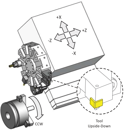
Figure 5: Lathe Coordinate System
8.3- Driven Tools
One variation of the CNC lathe is called a Mill−Turn center. In the milling mode, the spindle becomes a rotary axis that can stop, index, or move in sync with the other axes to create shapes including face milling, radial holes and slots. For example, Figure 6 shows a face milling operation. The X−C axes are coordinated to move the tool in a square shape on the part face.
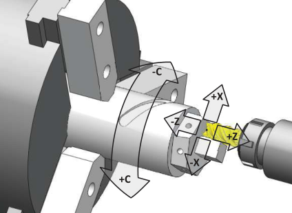
Figure 6: Driven Tool Machining
Mill−Turn centers can reduce production costs and make it easier to machine high tolerance parts compared with making the part on two different machines.
There are many configurations of mill−turn lathes, including machines with two tool turrets, two spindles, and even 5−axis milling. These can be challenging to program manually, but the CNC control includes functions to make programming easier. Many CAD/CAM systems support mill−turn centers, though the more exotic the machine configuration, the more difficult it may be to properly simulate and automatically generate edit−free G−code files using CAD/CAM.
8.4- Imaginary Tool Tip
The corners of lathe tools are radii. The imaginary tool tip is where vertical and horizontal lines tangent to the cutting edge of the tool intersect. This point is found by touching off the tool in the Z and X directions on the part or using a tool probe.
Because the imaginary tool tip can be found with great precision, it is used to control the tool. That is, all the Z−X coordinates in the G−code program are in reference to this point. Tool positions are easy to calculate parallel to the machine axes, but more complex for arcs and chamfers.
However, since almost everyone programs using CAD/CAM software or an on−control programming utility, you won’t have to calculate complex lathe tool paths. The programmer inputs the part profile geometry, and the control or software does all the calculations. Let the CAD/CAM software or control do this work.
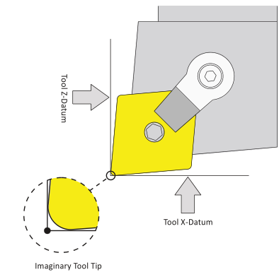
Figure 7: Imaginary Tool Tip
When programming a lathe, think in terms of motion of the imaginary tool tip. As shown in Figure 8, more positive Z−values move the tool to the right. More positive X−values move the tool away from the part.
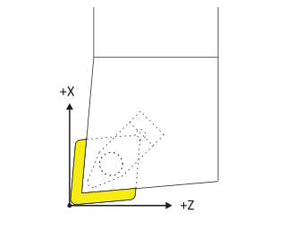
Figure 8: Tool Motion
8.5- Part Datum
The part datum is usually set as the center−face of the finished part, as shown in Figure 8 below.
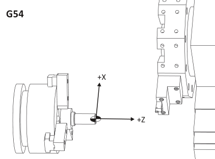
Figure 9: Part Datum
Lathe tools have two tool offsets: Z and X, which is the distance from the imaginary tool tip at home position to the part datum. There are two ways to set lathe tool offsets. The first involves making a small cut (try cut) on the OD and face of the stock material. The diameter is measured and entered in the control for the X−axis offset. Subsequent tool offsets are found in reference to these faces.
Many lathes now include a tool probe as standard or optional equipment. Please refer to your machine documentation for specific instructions about your machine and its options.
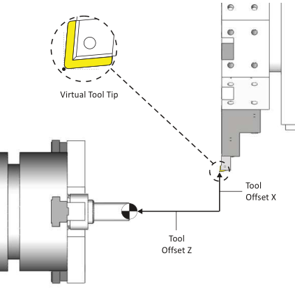
Figure 10: Tool Offsets
8.6- Tools and Tool Holders
While lathes use some of the same tools that mills use, including spot drills, drills, and taps, most turning is done using carbide inserts. Inserts are gripped in holders, which in turn are bolted to the lathe turret (see Fig. 4). Figure 11 shows a typical insert−holder combination. This is a left−handed holder, because the tool cutting edge points to the left when viewing the holder from the top as shown in Figure 12.
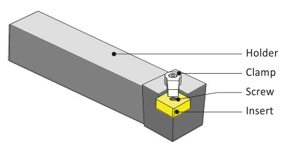
Figure 11: Typical Lathe Tool Holder
Carbide inserts employ highly engineered composite structures, coatings, and geometry features to achieve great accuracy and high material removal rates. Some inserts can be indexed to use other edges when one becomes worn. Inserts are quickly and easily replaced at the machine.
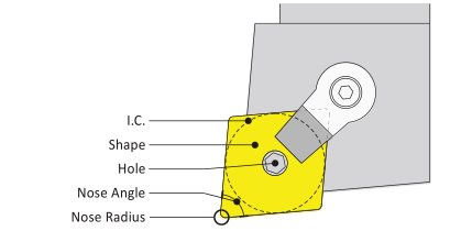
Figure 12: Insert Terms
Chip Breaker
A chip breaker is a feature in the face of the insert that disrupts the flow of chips such that they break into short segments, rather than forming a long, stringy chip.
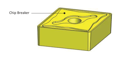
Figure 14: Chip Breaker
Relief Angle
Most inserts have drafted faces on the walls. This is called Relief Angle. Relief prevents the walls of the insert from rubbing against the part.
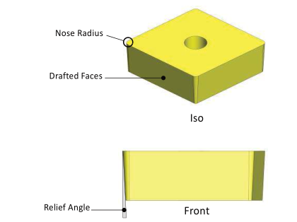
Figure 13: Relief Angle
Tool Cutting Angles
The edge of the tool in the cut direction forms an angle with a line perpendicular to the cut direction. This is called Side Cutting Angle. The angle formed by the trailing edge and parallel to the cut direction is called the End Cutting Angle.
جهت خرید قطعات سی ان سی و اطلاع از قیمت های لوازم cnc اینجا کلیک کنید.
The purpose of these angles is to provide proper clearance between the tool and work piece. For example, the 80 degree insert shown in Figure 16 is rigid and has enough side and end cutting angle for facing and rough turning operations. However, complex contours may require a 55 or 30 degree insert to provide tool side and end clearance for the tool and holder. Very steep or vertical walls may require a round or slot tool to carve.
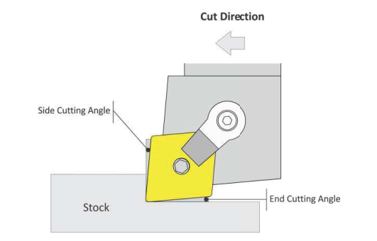
Figure 16: Cutting Angles
Rake Angle
Rake angle is set by the tool holder. Rake angle helps control the direction of the chip and cutting pressure. Angle is measured from face of the insert to the Z−X plane of the machine.
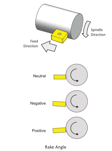
Figure 17: Rake Angle
8.7- Insert Designations
Carbide inserts use a coding system of numbers and letters to describe their shape, dimensions, and important parameters. For example, the designation of the insert shown in Figures 11−18 is a CNMG-433.
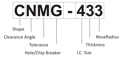
Figure 15: Carbide Insert Designation
Shape (CNMG-433)
There are at least 18 different shapes of carbide inserts. The most commonly used are shown in Table 1 with their letter designation. The angle in this designation refers to the included nose angle at the cutting radius of the tool.
|
|
Shape | |
|
T |
Triangle | |
|
S |
Square |
|
|
C |
80 degree diamond |
|
|
D |
55 degree diamond |
|
|
V |
35 degree diamond |
|
|
R |
Round | |
Table 1: Common Insert Shape Codes
Clearance Angle (CNMG-433)
Clearance angle is the draft on the face(s) of the insert that contact material during machining. More about insert angles a little later.
|
Designation |
Clearance Angle |
|
N |
0 Degrees (No Draft) |
|
A |
3 Degrees |
|
B |
5 Degrees |
|
C |
7 Degrees |
|
P |
11 Degrees |
Table 2: Common Insert Clearance Angles
Tolerance (CNMG-433)
This is how much variation is allowed in the dimensional size of the insert. Tolerances described with this parameter include the corner point (nose radius), thickness, and I.C. Typical tolerances are shown in Table 3:
|
Designation |
Cornerpoint |
Thickness |
I.C. |
|
M |
0.002 - 0.005 |
0.005 |
0.002 - 0.005 |
|
G |
0.001 |
0.005 |
0.001 |
|
E |
0.001 |
0.001 |
0.001 |
|
K |
0.0005 |
0.001 |
0.002 - 0.005 |
Table 3: Typical Insert Tolerances (Inch)
Hole/Chip Breaker (CNMG-433)
The hole/chip breaker designation describes both features with one letter. The hole in the insert and tool holder must match. If no letter exists in this field, then the insert does not have a hole to secure it to the holder, and is held by clamp force only.
| Designation |
Hole Shape |
Chipbreaker Type |
|
G |
Cylindrical |
Single−sided |
|
W |
40−60 deg, double c−sink |
None |
|
R |
None |
Single−sided |
|
T |
40−60 deg, double c−sink |
Single−sided |
|
P |
Cylindrical |
مثبت دوبل بالا |
|
Z |
Cylindrical |
مثبت دوبل بالا |
Table 4: Common Insert Hole/Chip Breaker Configurations
I.C. Size (CNMG-433)
Inserts are measured by the diameter of an inscribed circle. I.C.’s range from .0625” to 1.25”. Table 5 lists the sizes you are most likely to use.
| Designation | Decimal (inch) |
Fractional (inch) |
|
3 |
0.375 |
8/3 |
|
4 |
0.500 |
2/1 |
Table 5: Common Inscribed Circle Sizes
Thickness (CNMG-433)
Insert thickness.
|
Designation |
Decimal (inch) |
Fractional (inch) |
|
3 |
0.187 |
16/3 |
|
4 |
0.250 |
4/1 |
جدول 6- اندازههای دایرههای محاطی رایج
Nose Radius (CNMG-433)
Insert cutting nose radius.
|
Designation |
Decimal (inch) |
Fractional (inch) |
|
1 |
0.016 |
64/1 |
|
2 |
0.031 |
32/1 |
|
3 |
0.047 |
64/3 |
Table 7: Common Inscribed
The insert shapes, sizes, and designations in these tables are just of few of what is available. Any lathe tool catalog or manufacturers web site will show many more.
It is not important to memorize every tool shape or designation scheme. It is important to know insert terms and specifications to understand insert recommendations from the tool representative or technical resource to select the correct insert for the application.
8.8- Lathe Tool Types
The following is a list of the most common lathe−specific tool types. While these are the most common types you are likely to use, they represent only a small number of the tools that are available.
Note: For illustration purposes, the tools shown on the following pages are left−handed. Upper turret machines mostly use right−handed tools.
Face/Turn
For facing and rough turning, use a more rigid tool such as a round, square, or 80 degree diamond. Finishing may require a more versatile tool, such as a 55 or 35 degree diamond. These provide more side and end cutting angle relief to reach and contour part details. Inserts must match the tool holder, and that means the right type, size, shape, and clamping feature(s).
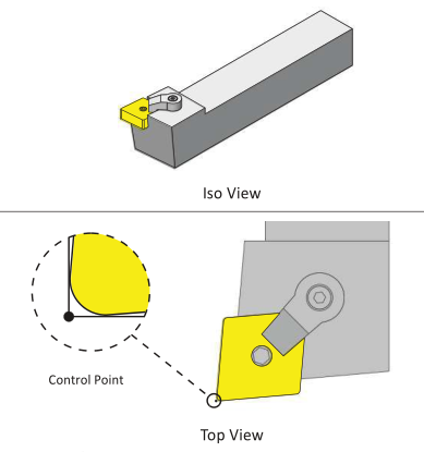
Figure 18: Face/Turn Tool (Left Hand)
Groove
Groove tools are classified in part by their width and corner radii. Though used mostly for making groove features, such as O−ring or snap−ring cuts, newer generations of these tools can be used for rough and finish contouring operations. While not the best choice for all roughing and finishing, they work well in areas where a diamond or other shape cannot easily fit.
Besides there being many types of groove tools, there are many types of holders, depending mostly on the cut direction for the tool. For example, there are groove holders for OD, ID, and Face grooves, and these are all available in Left Hand or Right Hand models.
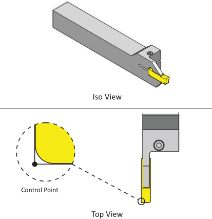
Figure 19: Groove Tool (Left Hand)
Bore
Precision holes are often finished with a boring tool. Boring bar tools are mounted parallel to the machine spindle. They require a hole in the part large enough to allow the bar to safely enter and exit the bore.
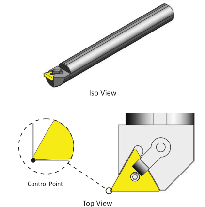
Figure 20: Boring Bar (Left Hand)
Thread
Tapped holes at the center of part, up to about one inch diameter, can be made using a form or cutting tap, just like on a mill. Larger ID threads and all ID threads use a thread insert.
Thread tools are set to the tip of the thread point in Z and X. Z is set by touching off on the edge of the part, and then taking into account the distance from this edge to the tip of the thread point, a distance included in the insert documentation.
Often a thread gage is used to check threads, and the X−offset for the thread tool adjusted to achieve the proper size and fit (Thread Class.
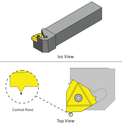
Figure 21: OD Thread Tool (Left Handed)
Cutoff
Once the part is finished, it is usually parted, or cut off from the stock. A cutoff tool is a special kind of groove tool that is designed to take deeper cuts. Cutoff tools are classified in part by their width and maximum cutting depth.
The blade shape of the cutoff tool allows it to cut deeper into the material than a groove tool. This shape does limit the side forces the tool can withstand.
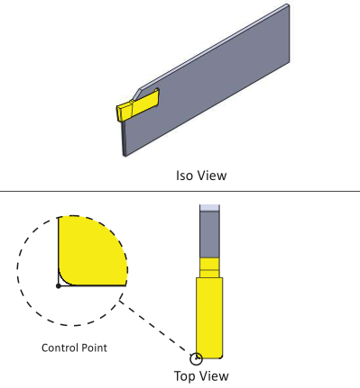
Figure 22: Cutoff Tool
8.9- Cutting Speeds and Feed
Speeds and feeds are calculated based on the maximum work diameter for the tool. Use the same speed formulas as for mills.

Figure 23: Speed Formula (Simplified)
Speed is the machine spindle RPM (how fast the part turns).
SFM is the Surface Feet per Minute based on the insert manufacturers’ recommendation for the material and cutting conditions.
3.82 is a constant that relates the surface feet per minute to work piece diameter.
Dia is the diameter of the tool when it first engages the material.
Figure 24: Facing Tool Engaging Material
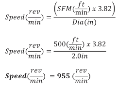
Speed/Feed Example
Problem:
Calculate the cutting speed for a facing operation given the following values:
|
Parameter |
Value |
| Part Diameter |
2.0in |
|
SFM |
500ft/min |
Table 8: Drill Speed/Feed Example
Solution:
Constant Surface Speed (CSS)
Notice that as the tool moves down the face of the part, the diameter where the cutting edge contacts the part gets smaller.
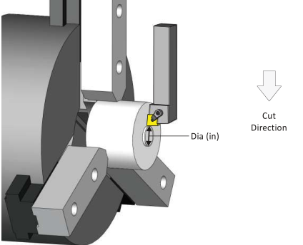
Figure 25: Decreasing Cut Diameter As Tool Nears Center
To maintain a constant rate of material removal as the cutting diameter decreases, most CNC machines automatically speed up the spindle, based on how far the tool moves towards center. This constantly variable spindle control is called Constant Surface Speed (CSS) mode. It is commanded on most machines using G96 to activate, and G97 to de−activate.
G96 is preceded by some important codes, as shown in the following example:
| Block |
Description |
|
G50 S2000 |
G50 sets the maximum spindle speed for this tool. |
|
G97 S1200 T101 M03 |
G97 cancels CSS so the spindle speed does not change as the turret rapids to position. |
|
GOO X2.1Z0. |
Tool moves to start of cut. |
|
M08 |
Coolant ON. |
|
G96 S1200 |
CSS mode on, Spindle begins at 1200 RPM. |
|
G01 X-.05 |
Face part. As tool moves from a diameter of 2.1 inches to X−.05, the spindle will increase speed up to the limit of S2000 RPM. |
Table 9: Lathe Program Using CSS
When invoked, you will hear the lathe spindle increase as the tool moves from the perimeter of the cut to the part center. The G50 command is important because it keeps the spindle from over−speeding.
Warning: All lathe chucks have speed limits based on the weight of the part and how far it extends from the face of the chuck. Do not exceed these limits. Ensure chuck clamping pressure is sufficient to grip the part based on cutting forces. Use G50 when using CSS mode to limit the speed of the spindle.
CSS does not apply where the tool does not change its position along X. For example, don’t use CSS mode for drilling or tapping on part centerline.
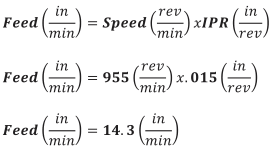
Feed is based on the speed and manufacturer’ recommended Feed Per Revolution (FPR) of the tool.
Cutting Feeds Example
Problem: Calculate the cutting feed for tool with the following parameters.
|
Parameter |
Value |
|
Speed |
955rpm |
|
IPR |
.015in/rev |
Table 10: Lathe Feed Example
Solution:
8.10- Lathe Setup & Programming Example
The following turned part is used on the following pages to introduce lathe tool paths. This example deals with processes in general, so material and dimensions are not important now.
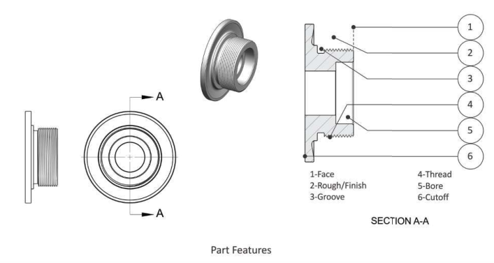
Figure 26: Example Lathe Part and Features
1- Face
Facing is usually the first lathe operation. It provides a known location to set the Z−offset of other tools and a flat surface for face drilling. Because sawed stock can vary in length, it is a common practice to take at least one roughing and finish facing pass.
2- Rough/Finish
The goal of lathe roughing is to remove excess material as efficiently as possible, ideally leaving a constant thickness of material for the finish tool. Finish tool paths determine the final size and surface finish.
3- Groove
Grooves have many configurations, but most have straight walls and radii at the bottom and top that is formed with the groove tool.
4- Thread
Threads on a lathe are usually machined with a special thread tool. Small diameter threads through the center of the part may be cut with a tap, just like on a mill.
5- Bore
Clearance holes in the bore may be drilled. Small bore holes may be reamed, but are usually finished with a boring bar tool.
6- Cutoff
The final operation is the cutoff. This may also put a chamfer or radius on the outside edge of the part. Once cut away from the stock, the part is allowed to simply fall into the bottom of the machine, though many lathes include a part catcher chute that extends during cutoff. The part falls onto this chute and rolls into cage for the operator to retrieve.
Setup
The part is gripped in hard jaws, soft jaws, or collet. Part datum is usually the center−face of the finished part. Provide enough excess stock to securely grip the part. The back side of the part should be as close to the jaws as possible while providing clearance for the cutoff tool.
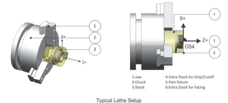
Figure 27: Typical Lathe Setup
1- Jaws
If using soft ways, machine them to fit the OD of the part. Jaws must have sufficient clamping pressure to hold the part. There is a limit to how far the jaws can be safely extended. This information is found in the chuck documentation.
2- Chuck
The chuck secures the jaws. A hole in the chuck allows bar material to extend through the chuck. This is useful for production runs. After a part is cut away, the jaws are opened, the stock drawn out further, and then the jaws are closed. This saves cutting the stock to length and wasted material.
3- Stock
Stock needs to be over−sized in Z and X so the face and finish tools remove material all around, including the cutoff.
4- Grip/Cutoff Stock
Ensure the back side of the part is far enough away from the jaws to provide cutoff tool clearance. Lathes are extremely powerful and any collision between the tool and rotating jaws is dangerous.
5- Part Datum
The part datum for lathe parts is usually the center−face of the finished part.
6- Extra Stock for Facing
Sawed stock is uneven and has a poor finish. Ensure the stock extends slightly beyond the finished face of the part so the face pass removes material.
Face
Facing is usually the first operation of any turning job.
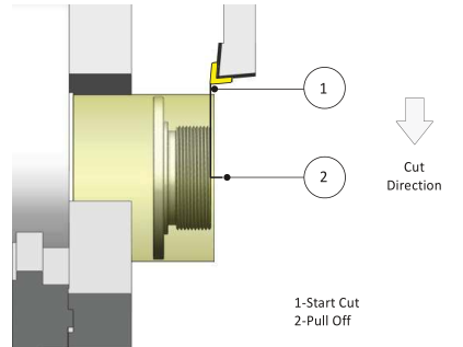
Figure 28: Face Toolpath
Rules for Facing
- Start away from the OD of the stock, keeping in mind that rough stock diameter varies.
- Face straight down until the contact point of the tool is at X0 and then pull pullaway.
- Consider taking one rough and one finish pass.
- Use a rigid tool, such as a 80 degree diamond.
Rough
Rough the part leaving stock in Z and X for finish paths.
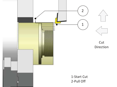
Figure 29: Roughing
Rules for Roughing
- Start away from the face of the part.
- A common practice is to use the same tool for both facing and OD roughing when possible.
- Leave a constant thickness of material over the part for the finishing operation.
- Skip over grooves and other features that will be rough or finished with other tools and operation.
- Consider moving the tool vertically at the end of each path to remove scallops.
- Extend the path past the back of the part for cutoff tool clearance.
Finish
Finish the part. Choose the largest and most rigid tool that will make all the features. Watch the back clearance of the tool to ensure the tool and holder do not collide with the part.
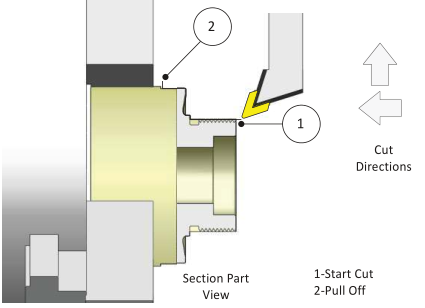
Figure 30: Finish
Rules for Finishing
- Start away from the part face.
- Use a tool, such as a 35 or 55 degree diamond, with sufficient side and end cutting angles to provide tool clearance.
- Use a tool with a nose radius equal, or preferably smaller, than the smaller ID radius in the profile.
- Consider taking a pre−finish pass first so the final pass removes a constant thickness of material.
- Skip over features, such as grooves, that will be machined using other tools and operations.
- For threads, finish at the major diameter of the thread.
Groove
Most grooves have radii at the top and bottom. Groove tool paths are actually quite complex. The following sequence is often used to create a groove that is accurate and with no tool marks.
جهت خرید قطعات سی ان سی و اطلاع از قیمت های لوازم cnc اینجا کلیک کنید.
A common groove operation is shown in the Details view in Figure 31: A) The tool is usually plunged near the center of the groove to rough. B) Other plunge moves as required to remove excess material. C) One contouring path, starting outside and moving inward, creating radii and contour. D) One contouring path, starting from the other side and moving inward finishing the other side.
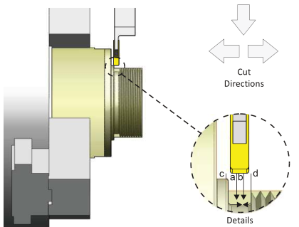
Figure 31: Groove
Rules for Grooving
- Use a groove tool narrower than the groove and with a radius equal or less than the finished radius.
- Use CAD/CAM or lathe control groove cycles to program the grooves.
Thread
Lathes are capable of creating any form thread, including tapered pipe threads, OD, ID, and multi−start. Most threading on a lathe is done with an insert. Several roughing passes that decrease in depth with each cut are followed by one or more finish passes that remove a small amount of material to form a thread that is accurate and smooth.
The motion of the tool and spindle are coordinated by the CNC control so that each time the tool begins the cut pass at the same rotational position.
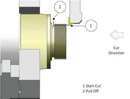
Figure 32: Thread
Rules for Threading
- Use the insert manufacturers’ recommendations for thread parameters.
- Use the CADƒCAM software or lathe control thread canned These work much like a mill drill cycle to program all the motion required for form the thread with just a few blocks of G−code.
- Start well away from the thread to give the spindle time to reach full speed before engaging the thread.
Drill
Lathes support common drill G−code cycles, including G81.
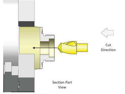
Figure 33: Drill
Rules for Drilling
- Spot drill holes.
- Consider using progressively larger drills to make a large holes.
- Peck drill deeper holes.
- Use a canned cycle when If programming using line and rapid moves, be sure to extract the tool completely from the bore before changing tools.
- Use the shortest drill possible to reduce tool chatter and produce a more accurate hole.
Bore
Bore operations produce precision holes with excellent surface finish.
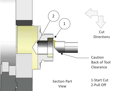
Figure 43: Boring
Rules for Boring
- Ensure the hole for the boring bar is large enough for tool clearance during all moves, including the lead− out move away from the finished
- Be sure to fully extract the bore bar out of the hole before sending it
- Precision holes require the correct amount of stock remaining and proper cutting speeds and
- Add roughing passes as needed before taking the finish cut to ensure constant material thickness for the finish
- Extend the tool path slightly beyond the back of the part to ensure a clean edge after cut
- For precision holes, such as press fits, consider backing off the X−offset several thousandths of an inch on the first part Machine the hole, check the actual finished bore diameter, and then adjust the offset as needed to produce the precision
Cutoff
This is always the last lathe machining operation. It frees the part from the stock material.
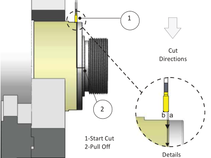
Figure 44: Cutoff
Rules for Cutoff
- Cutoff operations are much like grooving operations.
- As shown in the detail view above, cutoff usually begins with a cut that forms a radius or chamfer on the back side of the The tool then retracts, moves back, and then plunges to cut away the part.
- Consider using a parts catcher to keep the part from falling into the bottom of the machine and being scratched by the cut chips.