 فارسی
فارسی  English
 Upon successful completion of this lesson, you will be able to:
- Explain how 3D tool compensation is
- Describe 3D cut
- Identify geometric features common to 3D tool
- Explain the purpose, general parameters, and use of common 3D roughing tool
- Explain the purpose, general parameters, and use of common 3D finishing tool
- Explain the purpose, general parameters, and use of REST mill tool
- Explain the purpose, general parameters, and use of Pencil mill tool paths.
Overview
3D tool paths are used to machine non−prismatic parts such as molds, dies, and organically shaped consumer products. These parts may be composed of hundreds or thousands of faces.
CAD/CAM software creates 3D tool paths by first triangulazing the model, as shown in Figure 1 (though the mesh is far finer than shown in this illustration). This mesh is used to calculate the tool path based on tool size and shape.
3D tool paths are calculation intensive in part because of the extensive checking required to ensure the tool does not gouge the part as it moves across the topography of part faces.
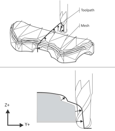
Figure 1: 3D Tool Path Calculation
9.1- 3D Cutter Compensation
3D paths control the center−tip of the tool. Figure 1 shows and compares how the tool path changes based on tool shape
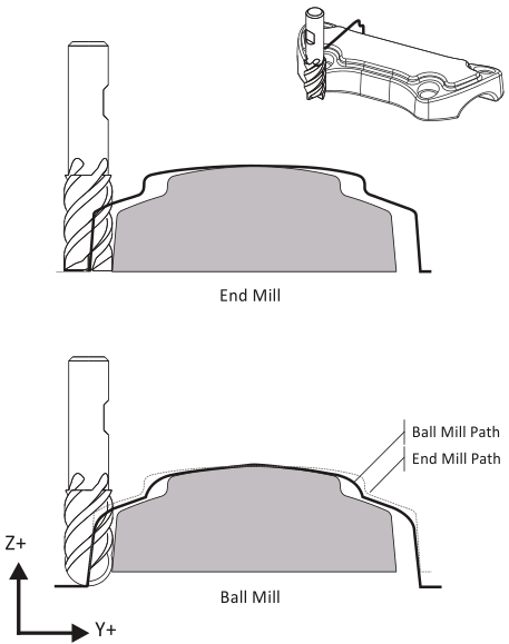
Figure 2: 3D Cutter Compensation
Cutter Diameter Compensation (G41/G42) is not supported for 3D tool paths by most CNC controls. The only way to compensate for a worn 3D finishing tool is to replace it.
9.2- Tolerances
3D tool paths are much about tradeoffs between quality and cost. As cut tolerances shrink, calculation time, file size, and run times balloon. Excessively fine tolerances may result in hundreds or thousands of blocks of code to move a short distance. This not only takes longer to calculate, it causes problems at the machine. It is therefore important to understand all tolerances involved with 3D tool paths, choose values appropriate to the task, and take actions to reduce CNC program file size while maintaining design intent.
جهت خرید قطعات سی ان سی و اطلاع از قیمت های لوازم cnc اینجا کلیک کنید.
CNC programs with unnecessarily fine tolerances should be avoided. CNC controls can only process a finite number of blocks of code per second. This processing speed, called the block execution time, varies between machines. Modern machines may be capable of processing several thousand blocks of code each second while older controls may be limited to less than a hundred.
If the number of blocks per second exceeds the machine capacity to process, a phenomenon known as data starving can occur: the control is overwhelmed with data and must pause after each move to wait for the next. This abrupt stopping and starting may happen hundreds of times per second.
Due to the mass of the machine components, the result is an effect similar to alternately pushing the accelerator then brake in a car. The machine may physically shake and shudder, a phenomenon called “bumping”. The actual feed rate of the machine may be a fraction of the programmed feed rate.
Data starving causes excessive CNC machine wear, poor surface finish, and excessive program run times. One solution at the machine is to use the machine manual feed rate override to feed rate until the shuddering stops. Some machines allow the control accelerationƒdeceleration function to be disabled or modified.
Much can be done at the CNC programming stage to avoid or correct this problem. Choose machining tolerances wisely. Use the CADƒCAM software tool path filtering function. Filtering works by analyzing the cut path and fitting long lines or tangent arcs where possible to replace short line moves. This may significantly reduce program size (by as much as 90%) while increasing the span of each move.
One consideration when choosing a tool path strategy is how well it will filter. Paths parallel to a CNC work plane (G17ƒG18ƒG19) filter far better than paths that are not.
Cut tolerance, illustrated in Figure 3, controls how closely the tool path follows a theoretically perfect path along the surface. Cut tolerance is a plus or minus value, so the total cut tolerance band is twice the tolerance value.
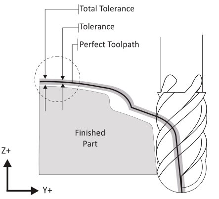
Figure 3: Cut Tolerance
9.3- 3D Toolpath Setups
A typical 3D setup is shown in Figure 4. Runoff surfaces are sometimes required to expand the tool paths to the XY extents of the stock, or to cause the tool to continue to machine down in Z along vertical walls.
Holes, fine details, or other features that will be created by subsequent operations may be suppressed or covered with a Check Surface to prevent the tool from entering these areas.
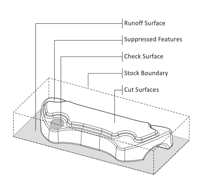
Figure 4: Typical 3D Tool Path Setup
9.4- 3D Roughing
3D tool paths can be grouped into two broad classifications: Roughing and Finishing. The aim of roughing tool paths is to remove excess material and, ideally, leave a constant thickness of stock all over the part for the finishing operations.
CAM systems include many strategies for roughing but by far the most common is some variation of 3D pocketing. These tool paths work by slicing the part by planes normal to the Z−axis. A boundary is created at each level, offset by the stock allowance, and 2D pocket tool path generated from this boundary. The result is a tiered cake shape as shown by the shaded image in Figure 5.
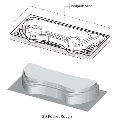
Figure 5: 3D Pocket Rough
9.5- Parallel Finish
The goal of 3D finishing tool paths is to remove material left by roughing paths and produce a part that meets design requirements for dimensional accuracy and surface finish.
A commonly used finish path is Parallel, shown in Figure 6. Parallel gets its name because, when viewed from above, tool paths appear parallel to each other.
جهت خرید قطعات سی ان سی و اطلاع از قیمت های لوازم cnc اینجا کلیک کنید.
Parallel tool paths calculate quickly and are reliable. However, they usually require additional finish passes to clean up heavy scallops (cusps).
Scallops can be seen Figure 7 and are most prominent on the closest wall. Small tool path step over values produce smaller scallops. Notice how scallop height changes depending on the topography of the part.
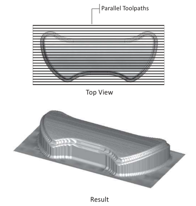
Figure 6: 3D Parallel Tool Path
Parallel tool paths tend to produce large scallops on steep walls roughly parallel to the path direction. As the tool steps to the next pass, the path drops down farther in Z on these walls compared with flat areas of the part. One approach to machining away these scallops is to create an additional parallel finish path rotated 90 degrees to the first. Of course this increases total program run time substantially.
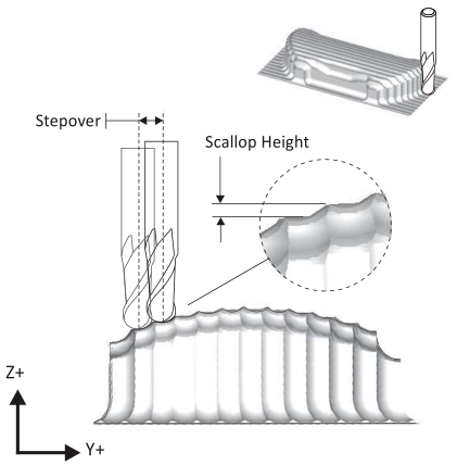
Figure 7: Scallop Height
9.6- 3D Scallop
Scallop tool paths, when viewed from the top, appear similar to 2D spiral pocket tool paths. Scallop paths continually change the stepover distance to maintain a constant scallop height over the entire part.
Scallop tool paths are calculation intensive and may not work on all shapes, and produce very large CNC programs with many short moves.
Yet, when applied properly, they work very well and produce a superior surface finish.
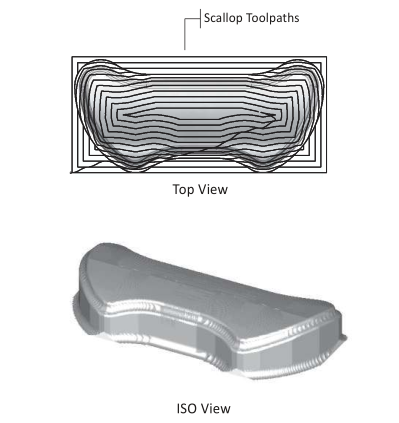
Figure 8: Scallop Tool Path
9.7- REST Milling
Rest Milling is an acronym for REmaining STock machining. Rest tool paths only remove material left by previous machining operations. They do this by calculating what stock has been previously removed and comparing it against the finished model. This is far more efficient than re−machining the entire part with a small tool just to create a few small features.
REST paths are calculation intensive. A good practice whenever possible is to use a tool whose diameter is slightly smaller than the smallest feature to be machined. This makes the REST calculations simpler and more effective.
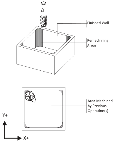
Figure 9: REST Milling
9.8- Pencil Toolpaths
Notice in Figure 8 that Scallop tool paths may also leave areas that require further finishing, though not as much as, say, a Parallel path.
Pencil Trace tool paths are a type of remaining stock machining (Rest Milling) that works by tracing a tool along the seams between surfaces that form an inside angle. Figure 10 shows a pencil tool path between along the inside fillet. This clears any remaining scallops in this area, leaving a perfect seam.
Like with REST machining, use a tool smaller than the radius when possible for Pencil tool paths.
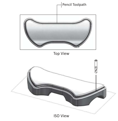
Figure 10: Pencil Trace Tool Path
9.9- Conceptualizing 3D Toolpaths
There is a story about a man admiring an artist cutting the sculpture of a bear from a log. Impressed and amazed by the artist’s ability, the man inquired how he was able to create such realism. The artist replied, “It’s easy, I just cut away anything that does not look like a bear!”
3D machining is a similar mindset. You begin with a block of material and cut away anything that does not belong. Begin by getting rid of excess material as quickly and efficiently as possible. Try to leave a constant thickness of material for finish operations. Finish as much of the part as possible using the largest tools possible. Then finish machine finer features and details using Parallel or Scallop paths contained by 2D profiles, or REST and Pencil tool paths.
3D machining can be very challenging, but in many cases it is easier than many 2D parts. Some 2D parts involve scores of machining operations that require considerable forethought and work. Most 3D parts require fewer operations and these are largely automated by CAD/CAM software functions.
The key to success is planning ahead and preparing the model before creating tool paths. In the case of 3D machining, perhaps 50−80% of the time programming is actually CAD−related, getting the model ready for tool paths: creating runoff surfaces, suppressing features, creating check surfaces, and the like.
Don’t begin making tool paths until you have a credible plan. If your planning is thorough and the CAD model is simplified so only those features to be machined are displayed, creating tool paths is far easier and outcomes better. To aid planning, use the forms in Appendix C, CNC Planning Forms.