 فارسی
فارسی  English
 Upon successful completion of this lesson, you will be able to:
- Explain Identify commonly used CNC work holding
- Identify the parts and accessories of a CNC
- Explain the difference between vise hard jaws, step jaws and soft jaws.
1.1- Overview
While there are many ways to hold a part during machining the ones illustrated in this chapter are the most commonly used for prototype and short−production machining. They work well for the types of parts you are likely to make.
Work holding for prototypes is often different than that for production machining. Large production lots allow the cost of tooling and fixtures to be amortized over many parts. While it is worth investing in complex fixtures to save seconds when making thousands of parts, it is not making only a few.
جهت خرید قطعات سی ان سی و اطلاع از قیمت های لوازم cnc اینجا کلیک کنید.
The goal with prototypes is to get the job done with minimal investments of time and money. This means using off−the−shelf components when possible and using methods that do not require a lot of time and effort.
There is often more than one work−holding method that will work for any given part. Review a tool supply catalog to familiarize yourself with the many types of clamps, bolts, and other holding devices that are available. The method you choose depends on many factors including personal preference, what work− holding components are readily available and cost.
In the end all that matters is that the method is safe, that it works, and that it is cost effective. Devising fixtures can be challenging. It requires being creative and thinking completely through all steps to machine the part. If you machine many parts, you will likely mix and match ideas learned here or from other sources.
1.2- Fixture Components
There are many fixture components for milling machines. This section covers some of the most common. If possible, acquire a fixture components catalog or look at the web sites of Carr−Lane (carrlane.com), Jergens (jergensinc.com), Chick (chickworkholding.com) MSC (mscdirect.com) and others.
Subplates and Angle Plates
A Subplate is a ground aluminum plate that bolts to the top of the machine table. It has threaded holes and bushings at regular intervals.
Subplates protect the machine table and speeds setups by allowing clamps and other components to be quickly and precisely located anywhere in the workspace.
Once installed, the subplate generally remains permanently fixed on the table. Fixtures and vises are installed on top of it.
An Angle plate is a precision ground steel plate that allows the part to be set on its side. Angle plates can point in a direction parallel to either the X or Y axis.
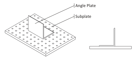
Figure 1: Angle Plate and Sub Plate
Clamps
There are literally thousands of types, styles, and sizes of clamps available. They are inexpensive, reusable, and versatile. You tool cabinet should include many types and sizes of clamps and accessories.
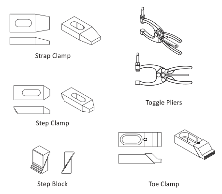
Figure 2: Clamps and Accessories
Strap Clamps exert downward pressure on the part. They are usually secured to the table by a special bolt that can be positioned anywhere along the T−slots in the table. One end of the clamp rests on the part, and the other on a step block.
To prevent galling an aluminum part, place a pad of aluminum between the clamp and part.
جهت خرید قطعات سی ان سی و اطلاع از قیمت های لوازم cnc اینجا کلیک کنید.
Step blocks have grooves that allow them to be stacked to different heights. Step blocks are used to support one end of the strap clamp.
Step Clamps are similar to Strap clamps, but include grooves that interlock with a single step block.
Toe Clamps bolt to the machine table. The nose of the clamp includes grooves to grip the part. It is extended by turning a screw, forcing the clamp against the part and downward.
Toggle Pliers are similar to hardware store vise grip pliers.
Shoulder Bolts and Dowel Pins
Dowel pins are used to precisely locate a part. They include a small chamfer to make insertion easier. Shoulder bolts both locate and grip the part. The ground shoulder on the bolt slides into a counterbore in the fixture.
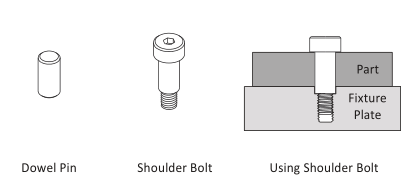
Figure 3: Dowel Pin and Shoulder Bolt
Vise and Accessories
The CNC vise is precision engineered and manufactured with components ground flat and perpendicular to within .0002 inches. The most common is referred to as a six inch vise, because the width of the jaws is six inches.
Once the vise is bolted to the table and aligned, parts are loaded into the vise and clamped by closing the jaws. The vise can exert tremendous force, so care is taken not to over−tighten the vise and deform fragile parts. Vise pressure must be appropriate to the part being held and expected cutting forces.
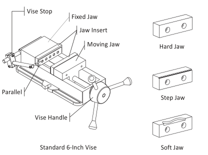
Figure 4: Vise and Accessories
The Fixed Jaw remains stationary. The Moving Jaw opens when the Vise Handle is turned. It is a good practice to remove the vise handle after the jaws are closed and before running the program. This is done by simply sliding the handle off.
A Vise Stop is a device that allows the parts to be loaded into the vise precisely. This image shows a style of vise stop that is particularly useful because it is adjustable up−down and left−right.
Hard Jaws are made of hardened steel and precision ground on all sides. They are usually used along with parallels.
Parallels are thin steel plates, available in various widths, used to set the grip length of the vise jaws.
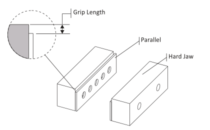
Figure 5: Hard Jaws
Step jaws are similar to hard jaws but include a step feature that eliminates the need for parallels.
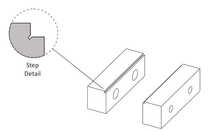
Figure 6: Step Jaws
Soft jaws are blanks of aluminum used to grip parts that cannot be held using hard jaws. A cutout the same shape as the part is machined into the soft jaws to grip irregular shapes.
جهت خرید قطعات سی ان سی و اطلاع از قیمت های لوازم cnc اینجا کلیک کنید.
When machining the cutout, place a bar between the jaws to set the correct spacing. Use a torque wrench or mark the vise so it can be closed with the exact same pressure each time a new part is loaded. Remove the spacer before clamping the part.
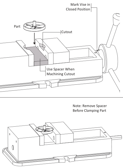
Figure 7: Machining Soft Jaws